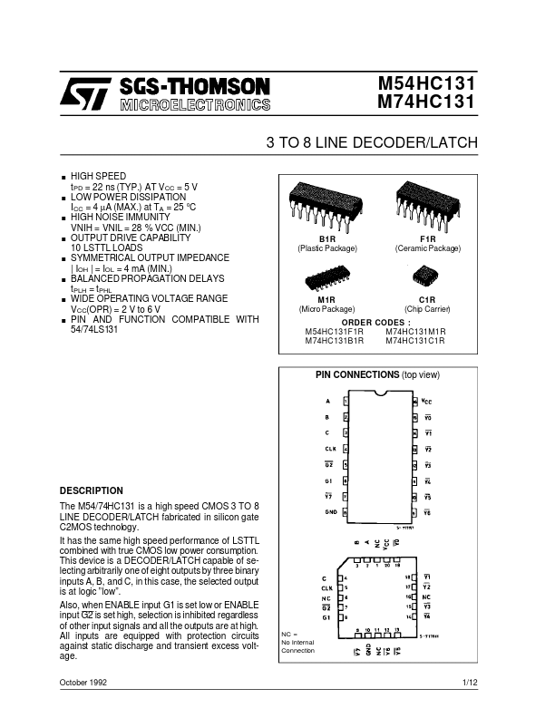
DESCRIPTION
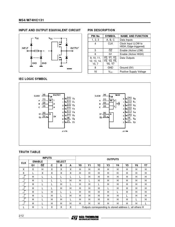
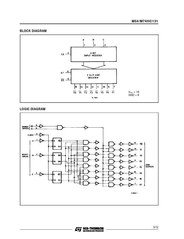
This device is a DECODER/LATCH capable of selecting arbitrarily one of eight outputs by three binary inputs A, B, and C, in this case, the selected output is at logic ”low”. Also, when ENABLE input G1 is set low or ENABLE input G2 is set high, selection is inhibited regardless of other input signals and all the outputs are at high. All inputs are equipped with protection circuits against static discharge and transient excess voltage. October 1992 NC = No Internal Connection 1/12 M54/M74HC131 INPUT AND OUTPUT EQUIVALENT CIRCUIT PIN DESCRIPTION
PIN No 1, 2, 3 4 5 6 9, 10, 11, 12, 13, 14, 15, 7 8 16 SYMBOL A, B, C CLK G2 G1 Y0, Y1, Y2, Y3, Y4, Y5, Y6, Y7 GND VCC NAME AND FUNCTION Data Inputs Clock Input (LOW to HIGH, Edge-triggered) Enable (Active LOW) Enable (Active HIGH) Data Outputs Ground (0V) Positive Supply Voltage IEC LOGIC SYMBOL TRUTH TABLE INPUTS ENABLE G1 X L H H H H H H H L H H G2 H X L L L L L L L L L C X X L L L L H H H H X SELECT B X X L L H H L L H H X A X X L... STMicroelectronics