DESCRIPTION
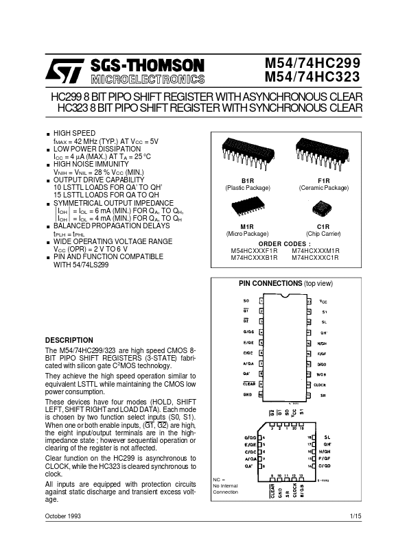
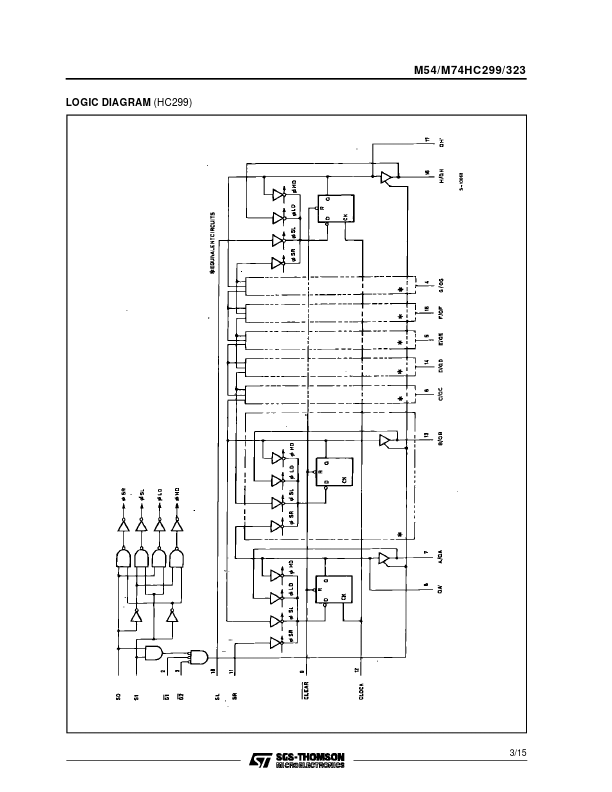
These devices have four modes (HOLD, SHIFT LEFT, SHIFT RIGHT and LOAD DATA). Each mode is chosen by two function select inputs (S0, S1). When one or both enable inputs, (G1, G2) are high, the eight input/output terminals are in the highimpedance state ; however sequential operation or clearing of the register is not affected. Clear function on the HC299 is asynchronous to CLOCK, while the HC323 is cleared synchronous to clock. All inputs are equipped with protection circuits against static discharge and transient excess voltage. October 1993 NC = No Internal Connection 1/15 M54/M74HC299/323 INPUT AND OUTPUT EQUIVALENT CIRCUIT TRUTH TABLE INPUTS MODE CLEAR L L L H H H H H H FUNCTION SELECTED S1 Z CLEAR HOLD SHIFT RIGHT SHIFT LEFT LOAD H L X L L L H H H S0 H X L L H H L L H OUTPUT CONTROL G1 * X L L L L L L L X G2 * X L L L L L L L X CLOCK (299) X X X X (323) INPUTS/OUTPUTS SERIAL SL X X X X X X H L X SR X X X X H L X X X Z L L QA0 H L QBn QBn a Z L L QH0 QGn QGn H L h L L L... STMicroelectronics