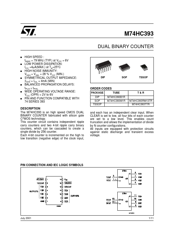
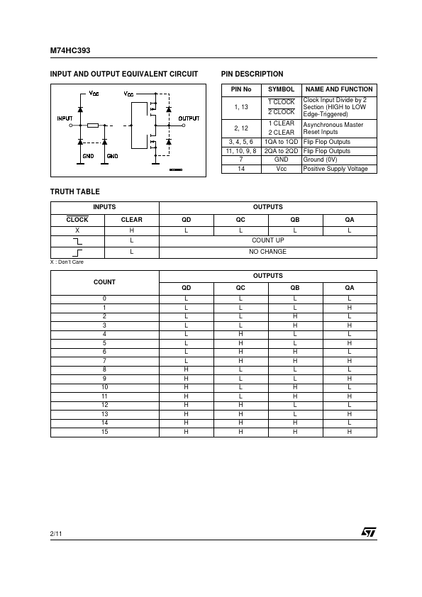
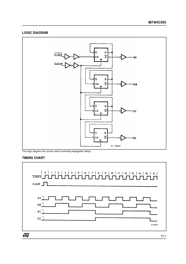
DESCRIPTION
When CLEAR is set to low, all four bits of each counter are set to a low level. This enables count truncation and allows the implementation of divide by N counter configurations. All inputs are equipped with protection circuits against static discharge and transient excess voltage. PIN CONNECTION AND IEC LOGIC SYMBOLS July 2001 1/11 M74HC393 INPUT AND OUTPUT EQUIVALENT CIRCUIT TRUTH TABLE INPUTS CLOCK X CLEAR H L X : Don’t Care L COUNT 0 1 2 3 4 5 6 7 8 9 10 11 12 13 14 15 QD L QD L L L L L L L L H H H H H H H H PIN DESCRIPTION
PIN No 1, 13 2, 12 3, 4, 5, 6 11, 10, 9, 8 7 14 SYMBOL NAME AND FUNCTION 1 CLOCK 2 CLOCK Clock Input Divide by 2 Section (HIGH to LOW Edge-Triggered) 1 CLEAR Asynchronous Master 2 CLEAR Reset Inputs 1QA to 1QD Flip Flop Outputs 2QA to 2QD Flip Flop Outputs GND Ground (0V) Vcc Positive Supply Voltage OUTPUTS QC QB LL COUNT UP NO CHANGE OUTPUTS QC QB LL LL LH LH HL HL HH HH LL LL LH LH HL HL HH HH QA L QA L H L H L H L H L H L H L H L H 2/11 LOGIC DIAG... STMicroelectronics