DESCRIPTION
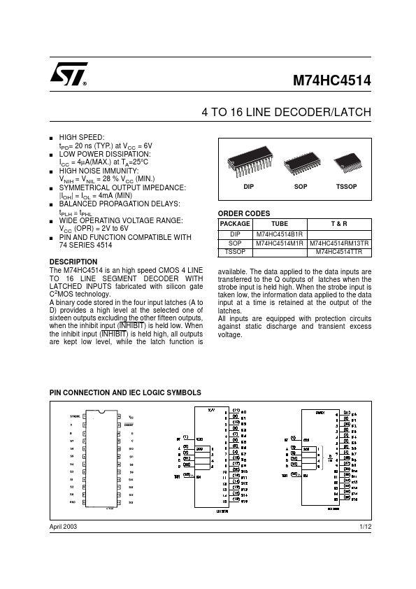
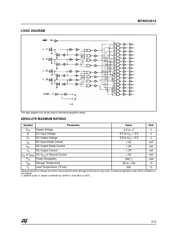
A binary code stored in the four input latches (A to D) provides a high level at the selected one of sixteen outputs excluding the other fifteen outputs, when the inhibit input (INHIBIT) is held low. When the strobe input is taken low, the information data applied to the data input at a time is retained at the output of the latches. All inputs are equipped with protection circuits against static discharge and transient excess voltage. PIN CONNECTION AND IEC LOGIC SYMBOLS April 2003 1/12 M74HC4514 INPUT AND OUTPUT EQUIVALENT CIRCUIT PIN DESCRIPTION
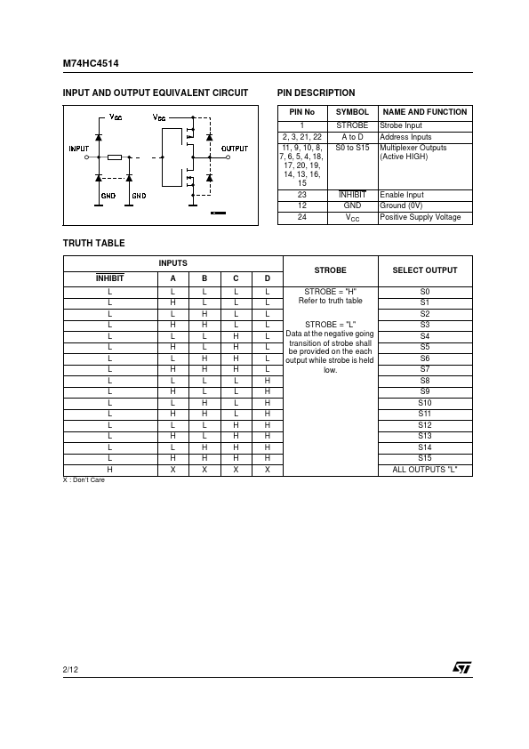
PIN No 1 2, 3, 21, 22 11, 9, 10, 8, 7, 6, 5, 4, 18, 17, 20, 19, 14, 13, 16, 15 23 12 24 SYMBOL STROBE A to D S0 to S15 NAME AND FUNCTION Strobe Input Address Inputs Multiplexer Outputs (Active HIGH) INHIBIT GND VCC Enable Input Ground (0V) Positive Supply Voltage TRUTH TABLE INPUTS STROBE INHIBIT L L L L L L L L L L L L L L L L H X : Don’t Care SELECT OUTPUT S0 S1 S2 S3 S4 S5 S6 S7 S8 S9 S10 S11 S12 S13 S14 S15 ALL OUTPUTS "L" A L... STMicroelectronics