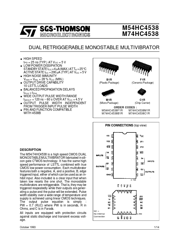
DESCRIPTION
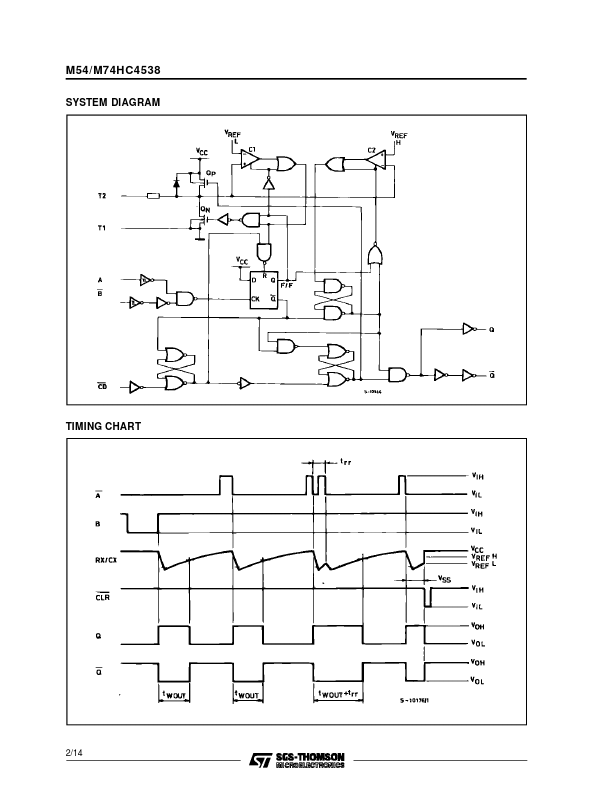
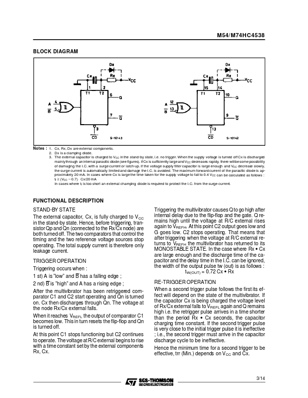
Each multivibrator features both a negative, A, and a positive, B, edge triggered input, either of which can be used as an inhibit input. Also included is a clear input that when taken low resets the one shot. The monostable multivibrators are retriggerable. That is, they may be triggered reapeatedly while their outputs are generating a pulse and the pulse will be extended. Pulse width stability over a wide range of temperature and supply is achieved using linear CMOS techniques. The output pulse equation is simply : PW = 0.7 (R)(C) where PW is in seconds, R in Ohms, and C is in Farads. All inputs are equipped with protection circuits against static discharge and transient excess voltage. October 1993 NC = No Internal Connection 1/14 M54/M74HC4538 SYSTEM DIAGRAM TIMING CHART 2/14 M54/ M74HC4538 BLOCK DIAGRAM Notes : 1. Cx, Rx, Dx are external components. 2. Dx is a clamping diode. 3. The external capacitor is charged to VCC in the stand-by state, i.e. no trigger. When the supply voltage is turned off Cx is discharged mainlythrough an internal parasitic diode (see figures). STMicroelectronics