DESCRIPTION
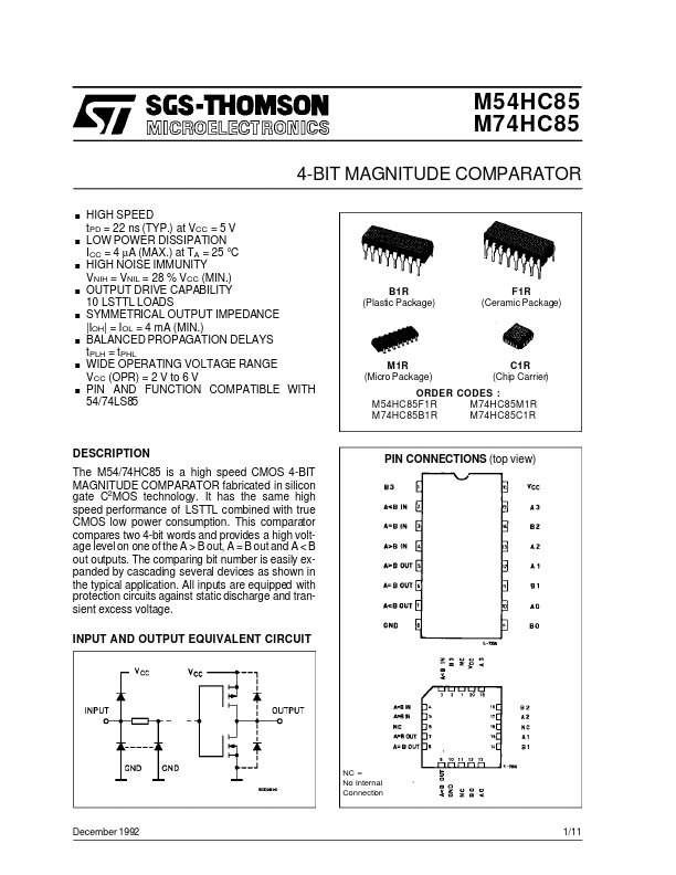
This comparator compares two 4-bit words and provides a high voltage level on one of the A > B out, A = B out and A < B out outputs. The comparing bit number is easily expanded by cascading several devices as shown in the typical application. All inputs are equipped with protection circuits against static discharge and transient excess voltage. INPUT AND OUTPUT EQUIVALENT CIRCUIT PIN CONNECTIONS (top view) NC = No Internal Connection December 1992 1/11 M54/M74HC85 PIN DESCRIPTION
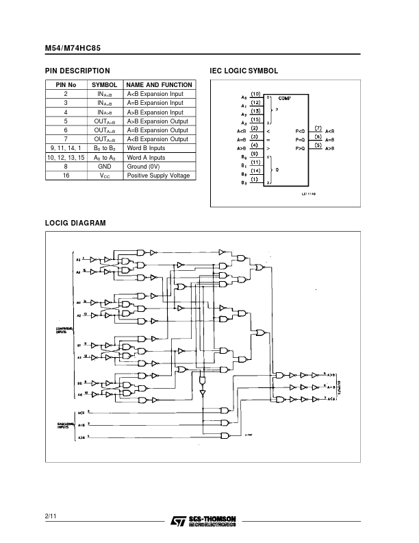
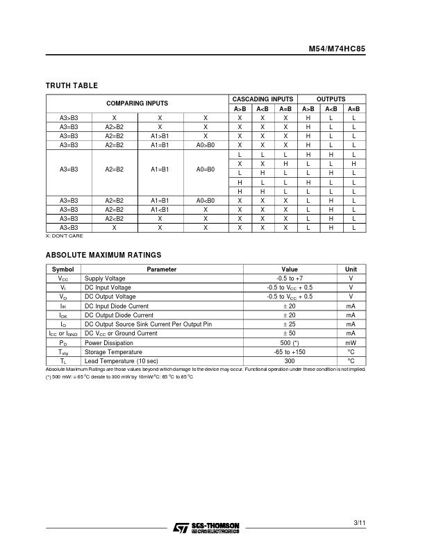
PIN No 2 3 4 5 6 7 9, 11, 14, 1 10, 12, 13, 15 8 16 SYMBOL IN A<B IN A=B IN A>B OUTA>B OUTA=B OUTA<B B0 to B3 A0 to A3 GND VCC NAME AND FUNCTION A<B Expansion Input A=B Expansion Input A>B Expansion Input A>B Expansion Output A=B Expansion Output A<B Expansion Output Word B Inputs Word A Inputs Ground (0V) Positive Supply Voltage IEC LOGIC SYMBOL LOCIG DIAGRAM 2/11 M54/M74HC85 TRUTH TABLE COMPARING INPUTS A3>B3 A3=B3 A3=B3 A3=B3 X A2>B2 A2=B2 A2=B2 X X A1>B1 A1=B1 X X X A0>B0 CASCADING INPUTS A>B X... STMicroelectronics