DESCRIPTION
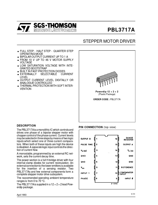
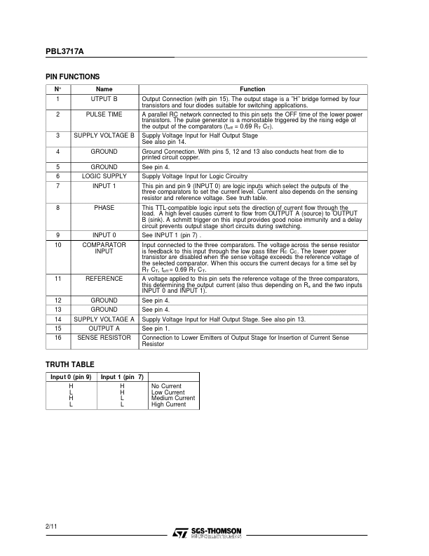
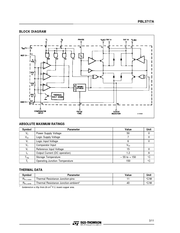
Current levels may be selected in threesteps by means of two logic inputs which select one of three current comparators. A separate logic input controls the direction of current flow. A monostable, programmed by an external RC network, sets the current decay time. The power section is a full H-bridge driver with four internal clamp diodes for current recirculation. An externalconnectionto the lower emitters is available for the insertion of a sensing resistor. Two PBL3717As and few external components form a complete stepper motor drive subsystem. The raccomended operating ambient temperature ranges is from 0 to 70 °C. The PBL3717Ais supplied in a 12 + 2 + 2 lead Powerdip package. April 1993 PIN CONNECTION (top view) 1/11 PBL3717A PIN FUNCTIONS N° 1 2 Name UTPUT B PULSE TIME Function Output Connection (with pin 15). The output stage is a ”H” bridge formed by four transistors and four diodes suitable for switching applications. A parallel RC network connected to this pin sets the OFF time of the lower power transistors. STMicroelectronics