STMicroelectronics SM6T10CA
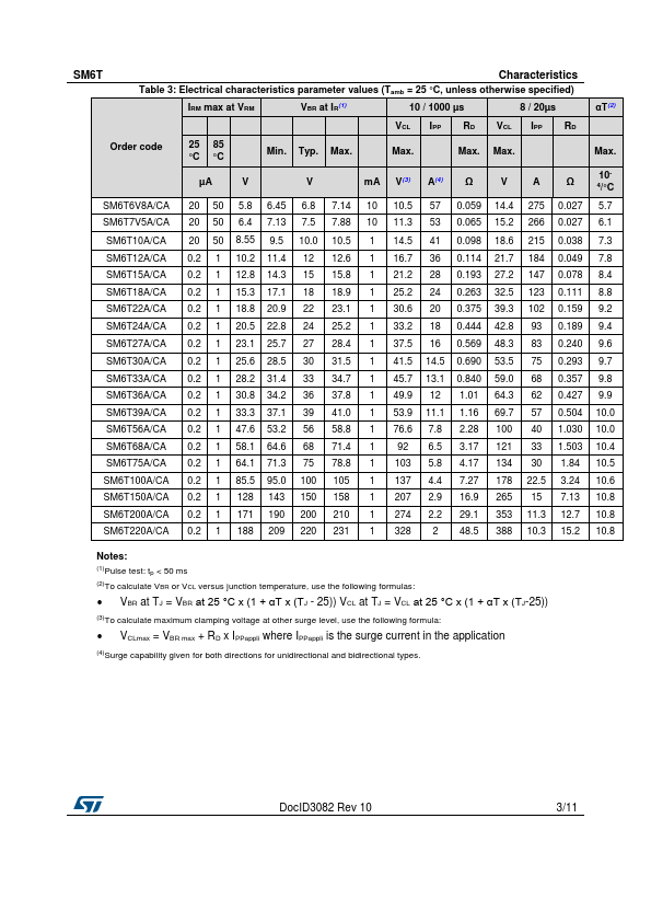
The curves of the figure 3 are specified for a junction temperature of 25°C before surge. The given results may be extrapolated for other junction temperatures by using the following formula : ∆VBR = αT * [Tamb -25] * VBR(25°C) For intermediate voltages, extrapolate the given results.| Part No. | SM6T10CA |
|---|---|
| Datasheet | SM6T10CA Download |
| Manufacturer |  STMicroelectronics |
| Description | TRANSIL |
| Buy | Stock & Price |
FEATURES
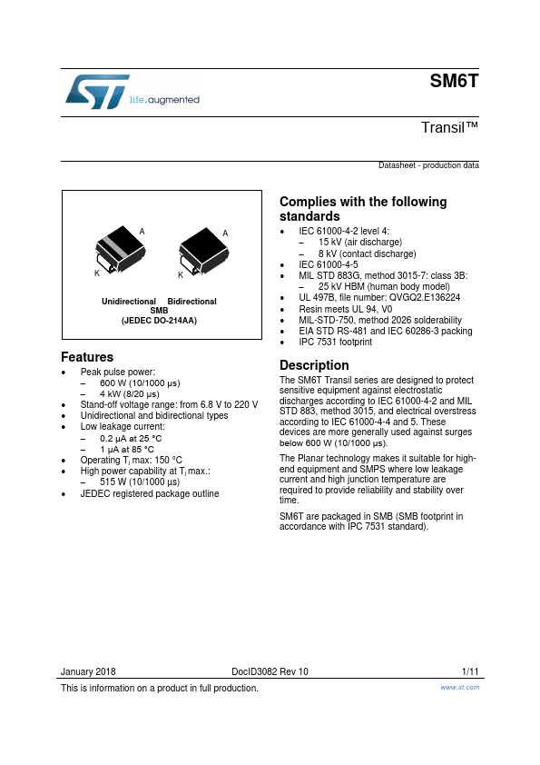
s s s s s s PEAK PULSE POWER : 600 W (10/1000µs) BREAKDOWN VOLTAGE RANGE : From 6.8V to 220 V. UNI AND BIDIRECTIONAL TYPES LOW CLAMPING FACTOR FAST RESPONSE TIME UL RECOGNIZEDDESCRIPTION
Transil diodes provide high overvoltage protection by clamping action. Their instantaneous response to transient overvoltages makes them particularly suited to protect voltage sensitive devices such as MOS Technology and low voltage supplied IC’s.ABSOLUTE MAXIMUM RATINGS
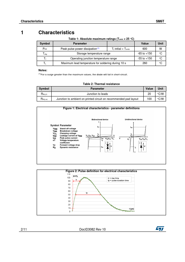
(Tamb = 25°C) Symbol PPP P IFSM Parameter Peak pulse power dissipation (see note 1) Power dissipation on infinite heatsink Non repetitive surge peak forward current for unidirectional types Storage temperature range Maximum junction temperature Maximum lead temperature for soldering during 10 s. SMB (JEDEC D0-214AA) Value Tj initial = Tamb Tamb = 50°C tp = 10ms Tj initial = Tamb 600 5 100 Unit W W A Tstg Tj TL - 65 to + 175 150 260 °C °C °C Note 1 : For a surge greater than the maximum values, the diode will fail in short-circuit.