DESCRIPTION
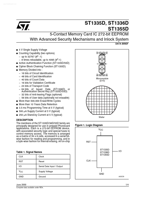
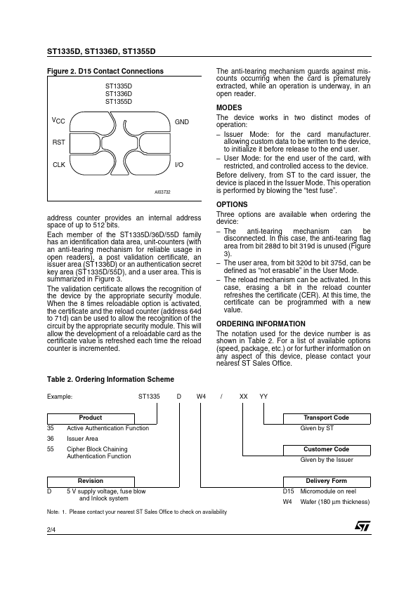
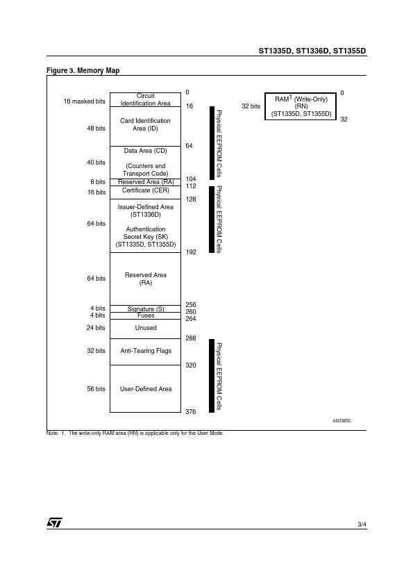
The members of An on-chip Figure 1. Logic Diagram VCC RST Table 1. Signal Names CLK RST I/O VCC GND Clock Reset Serial Data Input / Output Supply Voltage ST1335D ST1336D ST1355D CLK I/O GND Ground AI03729 June 2000 Complete data available under NDA . 1/4 ST1335D, ST1336D, ST1355D Figure 2. D15 Contact Connections ST1335D ST1336D ST1355D VCC RST GND The anti-tearing mechanism guards against miscounts occurring when the card is prematurely extracted, while an operation is underway, in an open reader. MODES The device works in two distinct modes of operation: – Issuer Mode: for the card manufacturer. allowing custom data to be written to the device, to initialize it before release to the end user. – User Mode: for the end user of the card, with restricted, and controlled access to the device. Before delivery, from ST to the card issuer, the device is placed in the Issuer Mode. This operation is performed by blowing the “test fuse”. OPTIONS Three options are available when ordering the device: – The anti-tearing mechanism can be disconnected. STMicroelectronics