DESCRIPTION
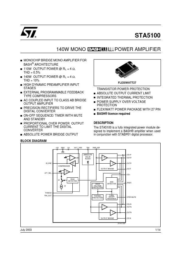
BLOCK DIAGRAM +VS GND -VS OUT_ PRE TRK PWR_INP + IN_PRE COMPRESSOR ∆G ABSOLUTE VALUE BLOCK CD+P +2 OUTP +2 OUTP OUTPUT BRIDGE ATT_REL V/l CD-P CD+ PEAK DETECTOR Ict OVER VOLTAGE PROTECTION S1 SOA DETECTOR PROT. THRESH TRK_OUT THERMAL PROTECTION TURNON/OFF SEQUENCE STBY/MUTE CD+N -1 OUTN -1 OUTN OUTPUT BRIDGE CD-N D01AU1280 July 2003 1/14 STA5100 DESCRIPTION
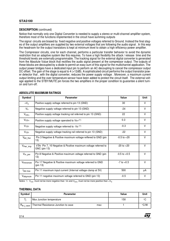
(continued) Notice that normally only one Digital Converter is needed to supply a stereo or multi-channel amplifier system, therefore most of the functions implemented in the circuit have summing outputs The signal circuits are biased by fixed negative and positive voltages referred to Ground. Instead the final stages of the output amplifiers are supplied by two external voltages that are following the audio signal . In this way the headroom for the output transistors is kept at minimum level to obtain a high efficiency power amplifier. The Compressor circuits, one for each channel, performs a particular transfer behavior to avoid the dynamic restriction that an adaptive system like this requires. STMicroelectronics