STMicroelectronics STGP10N60L
N-CHANNEL IGBT
| Part No. | STGP10N60L |
|---|---|
| Datasheet | STGP10N60L Download |
| Manufacturer |  STMicroelectronics |
| Description | N-CHANNEL IGBT |
| Buy | Stock & Price |
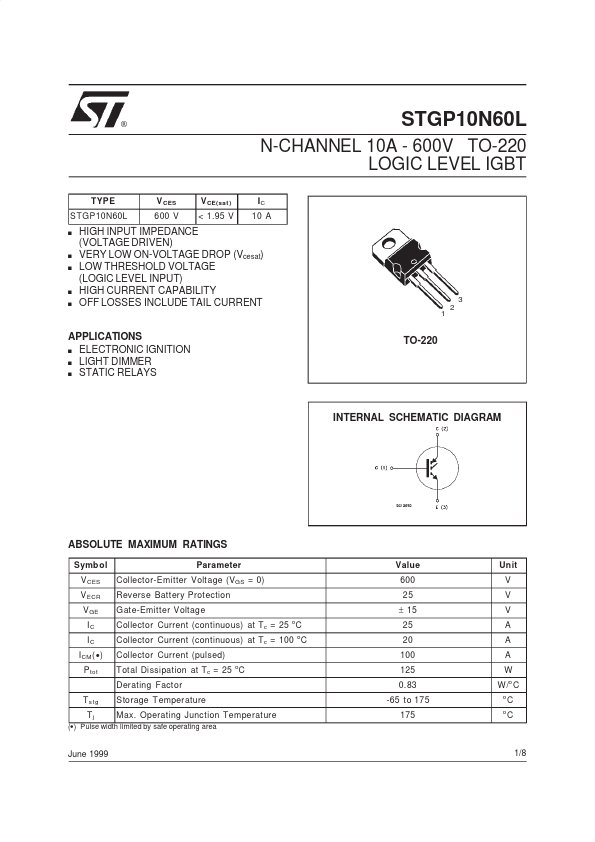
APPLICATIONS
s ELECTRONIC IGNITION s LIGHT DIMMER s STATIC RELAYS TO-220 INTERNAL SCHEMATIC DIAGRAMABSOLUTE MAXIMUM RATINGS
Symb ol V CES V ECR V GE IC IC I CM (● ) P tot T s tg Tj Parameter Collector-Emitter Voltage (VGS = 0) Reverse Battery Protection G ate-Emitter Voltage Collector Current (continuous) at Tc = 25 C Collector Current (continuous) at Tc = 100 C Collector Current (pulsed) T otal Dissipation at Tc = 25 C Derating Factor Storage T emperature Max. Operating Junction Temperature o o o Value 600 25 ± 15 25 20 100 125 0.83 -65 to 175 175 Un it V V V A A A W W /o C o o C C (●) Pulse width limited by safe operating area June 1999 1/8 STGP10N60L THERMAL DATA R thj -case R thj -amb R thc-sink Thermal Resistance Junction-case Thermal Resistance Junction-ambient Thermal Resistance Case-sink Max Max T yp 1.2 62.5 0.1 o o C/W C/W o C/W
ELECTRICAL CHARACTERISTICS
(Tj = - 40 to 150 oC unless otherwise specified) OFF Symbo l V BR(c es) I CES IGES Parameter Collector-Emitt er Breakdow...