STSR2PM
STSR2PM is FORWARD SYNCHRONOUS RECTIFIERS SMART DRIVER manufactured by STMicroelectronics.
- Part of the STSR2P comparator family.
- Part of the STSR2P comparator family.
STSR2P/ STSR2PM
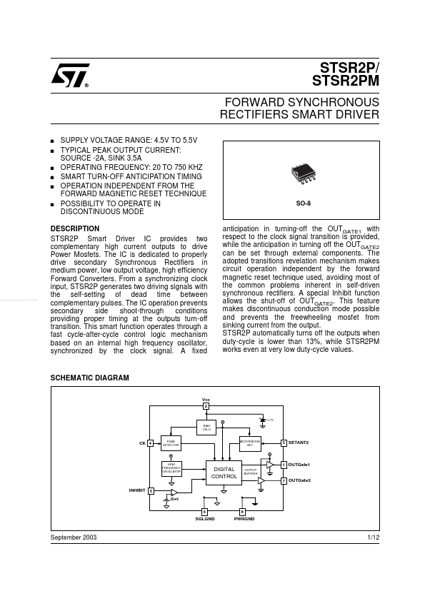
FORWARD SYNCHRONOUS RECTIFIERS SMART DRIVER s s s s s s
SUPPLY VOLTAGE RANGE: 4.5V TO 5.5V TYPICAL PEAK OUTPUT CURRENT: SOURCE -2A, SINK 3.5A OPERATING FREQUENCY: 20 TO 750 KHZ SMART TURN-OFF ANTICIPATION TIMING OPERATION INDEPENDENT FROM THE FORWARD MAGNETIC RESET TECHNIQUE POSSIBILITY TO OPERATE IN DISCONTINUOUS MODE
SO-8
..
DESCRIPTION STSR2P Smart Driver IC provides two plementary high current outputs to drive Power Mosfets. The IC is dedicated to properly drive secondary Synchronous Rectifiers in medium power, low output voltage, high efficiency Forward Converters. From a synchronizing clock input, STSR2P generates two driving signals with the self-setting of dead time between plementary pulses. The IC operation prevents secondary side shoot-through conditions providing proper timing at the outputs turn-off transition. This smart function operates through a fast cycle-after-cycle control logic mechanism based on an internal high frequency oscillator, synchronized by the clock signal. A fixed anticipation in turning-off the OUT GATE1 with respect to the clock signal transition is provided, while the anticipation in turning off the OUTGATE2 can be set through external ponents. The adopted transitions revelation mechanism makes circuit operation independent by the forward magnetic reset technique used, avoiding most of the mon problems inherent in self-driven synchronous rectifiers. A special Inhibit function allows the shut-off of OUTGATE2. This feature makes discontinuous conduction mode possible and prevents the freewheeling mosfet from sinking current from the output. STSR2P automatically turns off the outputs when duty-cycle is lower than 13%, while STSR2PM works even at very low duty-cycle values.
SCHEMATIC DIAGRAM
Vcc
+
BIAS UVLO
5.7V
CK 4
PEAK DETECTOR
ANTICIPATION SET
3 SETANT2
+
+
HIGH FREQUENCY OSCILLATOR
1 OUTGate1
DIGITAL CONTROL
OUTPUT BUFFERS
7 OUTGate2
INHIBIT 5
+ 25m...