DESCRIPTION
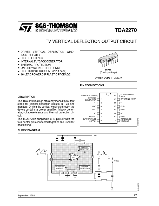
Driving the vertical windings directly, the device contains a power amplifier, flyback generator, voltage reference and thermal protection circuit. BLOCK DIAGRAM SUPPLY VOLTAGE FLYBACK GENERATOR NC GND GND NC OUTPUT OUTPUT STAGE SUPPLY 1 2 3 4 5 6 7 8 16 15 NON-INVER TING INPUT INVERTING INPUT NC GND GND NC 2270-01.EPS 14 13 12 11 10 9 GND REFERENCE VOLTAGE +VS 1 8 2 FLYBACK GENERATOR 15 POWER AMP. 7 YOKE 16 REFER ENCE VOLTAGE THERMAL PROTECTION 4 9 12 13 10 5 September 1992 1/7 2270-02.EPS TDA2270 ABSOLUTE MAXIMUM RATINGS
Symbol Vs V7 , V8 V2 V15, V16 Io Io Io I2 I2 Ptot Tstg, Tj Supply Voltage (pin 1) Flyback Peak Voltage Voltage at Pin 2 Amplifier Input Voltage Output Peak Current (non repetitive, t = 2 ms) Output Peak Current at f = 50 Hz, t ≤ 10 µs Output Peak Current at f = 50 Hz, t > 10 µs Pin 2 DC Current at V7 < V1 Pin 2 Peak to Peak Flyback Current at f = 50 Hz, tfly ≤ 1.5 ms Total Power Dissipation at Tpins ≤ 90 °C Tamb = 70 °C Parameter Value 35 60 + Vs + Vs, –... STMicroelectronics