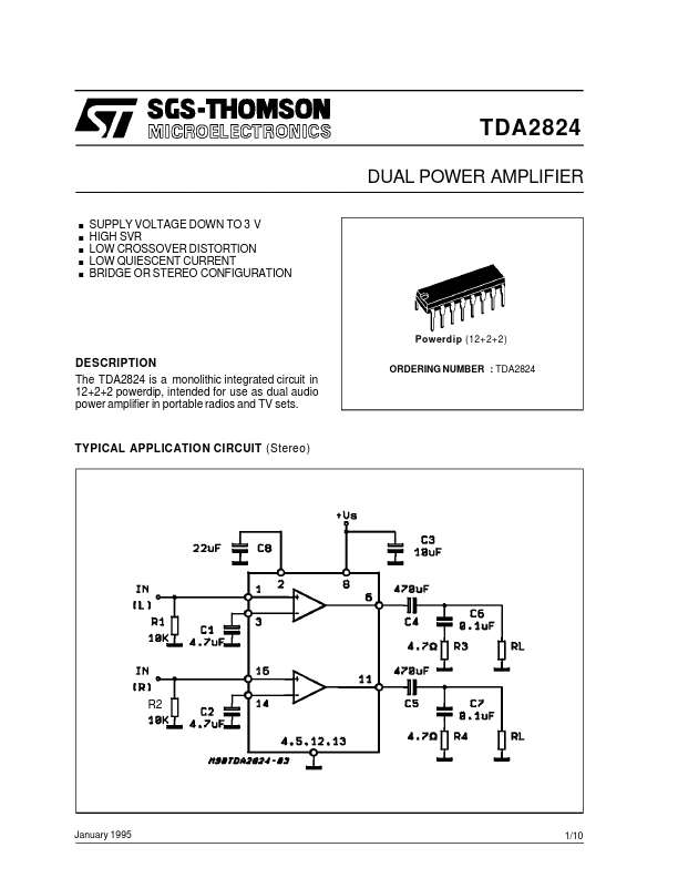
DESCRIPTION
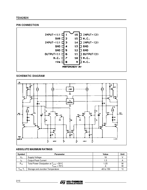
ORDERING NUMBER : TDA2824 TYPICAL APPLICATION CIRCUIT (Stereo) R2 January 1995 1/10 TDA2824 PIN CONNECTION SCHEMATIC DIAGRAM ABSOLUTE MAXIMUM RATINGS
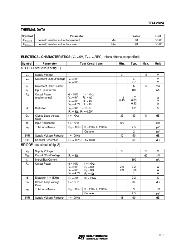
Symbol VS IO Ptot Tstg, Tj Supply Voltage Output Peak Current Total Power Dissipation at Tamb = 50°C Tamb = 70°C Storage and Junction Temperature Parameter Value 16 1.5 1.25 4 -40 to 150 Unit V A W W °C 2/10 TDA2824 THERMAL DATA Symbol R th j-amb Rth j-case Parameter Thermal Resistance Junction-ambient Thermal Resistance Junction-case Max. Max. Value 80 20 Un it °C/W °C/W ELECTRICAL CHARACTERISTICS
(VS = 6V, Tamb = 25°C, unless otherwise specified) Symbol Parameter Test Co nditi ons Min. Typ . Max. Un it STEREO (test circuit of fig. 1) VS VO Id Ib PO Supply Voltage Quiescent Output Voltage Quiescent Drain Current Input Bias Current Output Power (each channel) d = 10% VS = 9V VS = 6V VS = 4.5V f = 1KHz RL = 4Ω RL = 4Ω RL = 4Ω 1.3 0.45 VS = 9V VS = 9V 3 4 2.7 6 100 1.7 0.65 0.32 0.2 36 100 B = 22Hz to 22KHz Curve A SVR CS Supply... STMicroelectronics