ABSOLUTE MAXIMUM RATINGS
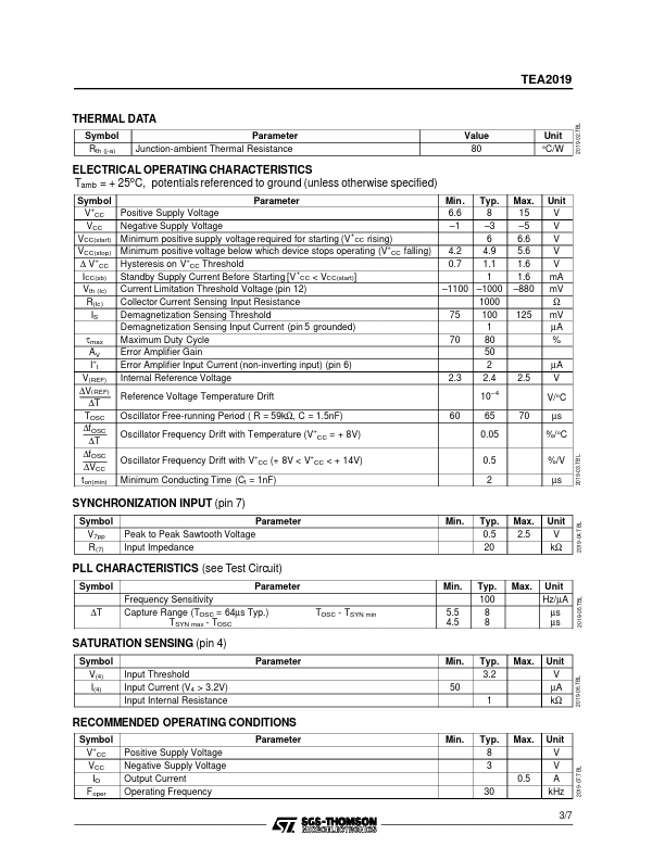
Symbol + V CC V(aux) – V CC IO (peak) II Tj Toper Tstg 2/7 Parameter Positive Supply Voltage Auxiliary Output Supply Voltage Negative Supply Voltage Peak Output Current (duty cycle < 5%) Input Current Pins 4-5 Junction Temperature Operating Ambient Temperature Range Storage Temperature Range Value 15 15 –5 ±1 ±5 150 – 20, + 70 – 40, + 150 Unit V V V A mA °C °C °C 2019-01.TBL 2019-02.EPS TEA2019 THERMAL DATA Symbol Rth (j-a) Parameter Junction-ambient Thermal Resistance Value 80 Unit °C/W ELECTRICAL OPERATING CHARACTERISTICS Tamb = + 25oC, potentials referenced to ground (unless otherwise specified) Symbol + V CC VCC VCC(start) VCC(stop) + ∆ V CC ICC(sb) Vth (Ic) R(Ic ) IS τmax AV + II V(REF) ∆V(REF) ∆T TOSC ∆fOSC ∆T ∆fOSC ∆VCC ton(min) Parameter Positive Supply Voltage Negative Supply Voltage + Minimum positive supply voltage required for starting (V CC rising) Minimum positive voltage below which device stops operating (V+CC falling) + Hysteresis on V CC Thres... STMicroelectronics