TP30-100
FEATURES
BIDIRECTIONAL CROWBAR PROTECTION. VOLTAGE RANGE: FROM 62 V TO 270 V. HOLDING CURRENT : IH = 150 m A min. REPETITIVE PEAK PULSE CURRENT : IPP = 30 A, 10/1000 µs. JEDEC REGISTERED PACKAGE OUTLINE DESCRIPTION
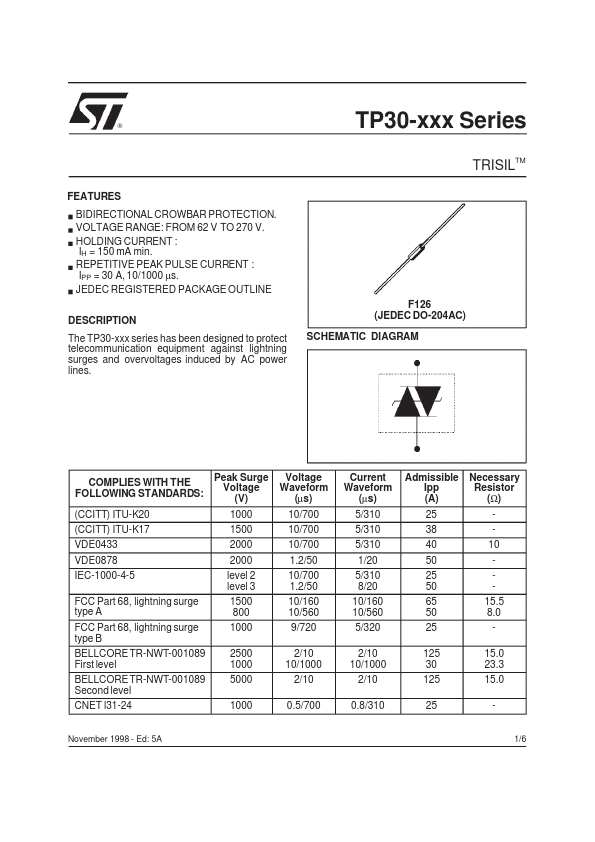
The TP30-xxx series has been designed to protect telemunication equipment against lightning surges and overvoltages induced by AC power lines. F126 (JEDEC DO-204AC) SCHEMATIC DIAGRAM
PLIES WITH THE FOLLOWING STANDARDS: (CCITT) ITU-K20 (CCITT) ITU-K17 VDE0433 VDE0878 IEC-1000-4-5 FCC Part 68, lightning surge type A FCC Part 68, lightning surge type B BELLCORE TR-NWT-001089 First level BELLCORE TR-NWT-001089 Second level CNET l31-24
November 1998
- Ed: 5A
Peak Surge Voltage (V) 1000 1500 2000 2000 level 2 level 3 1500 800 1000 2500 1000 5000 1000
Voltage Waveform (µs) 10/700 10/700 10/700 1.2/50 10/700 1.2/50 10/160 10/560 9/720 2/10 10/1000 2/10 0.5/700
Current Waveform (µs) 5/310 5/310 5/310 1/20 5/310 8/20 10/160 10/560 5/320 2/10 10/1000 2/10 0.8/310
Admissible Ipp...