DESCRIPTION
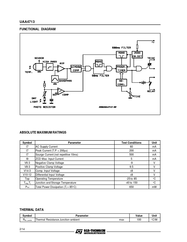
BLOCK DIAGRAM DIP-14 SO-14 ORDERING NUMBERS: UAA4713DP UAA4713FP If the sensor detects a temperature change, a programmable timer will start and switch a lamp or other loads to the mains. A further input for a photo-resistive sensor allows to program circuit operation depending on the day-light intensity. Internal circuits avoid false triggering of the external actuators. (see functional diagram). December 1991 1/14 This is advanced information on a new product now in development or undergoing evaluation. Details are subject to change without notice. UAA4713 FUNCTIONAL DIAGRAM ABSOLUTE MAXIMUM RATINGS
Symbol I7 I7 I7 I9 V6-3 V8-3 V14-3 V10-12 Top Tstg,T j Ptot AC Supply Current Peak Current (T.P < 200µs) Sourge Current (not repetitive 10ms) ZCD Max. Input Current Negative Clamp Voltage Positive Clamp Voltage Comp. Input Voltage Differential Input Voltage Operating Temperature Junction and Storage Temperature Total Power Dissipation (Tj = 85°C) Parameter Test Conditions 60 2... STMicroelectronics