DESCRIPTION
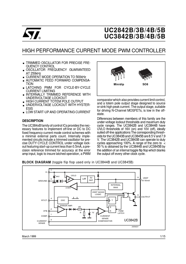
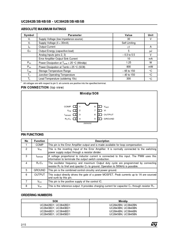
Internally implemented circuits include a trimmed oscillator for precise DUTY CYCLE CONTROL under voltage lockout featuring start-up current less than 0.5mA, a precision reference trimmed for accuracy at the error amp input, logic to insure latched operation, a PWM Minidip SO8 comparator which also provides current limit control, and a totem pole output stage designed to source or sink high peak current. Differences between members of this family are the under-voltage lockout thresholds and maximum duty cycle ranges. The UC3842B and UC3843B can operate to duty cycles approaching 100%. A range of the zero to < 50 % is obtained by the UC3844B and UC3845B by the addition of an internal toggle flip flop which blanks the output off every other clock cycle. BLOCK DIAGRAM (toggle flip flop used only in UC3844B and UC3845B) 7 Vi 5 GROUND 4 RT/CT 2 VFB 1 COMP CURRENT 3 SENSE 34V UVLO S/R 5V REF 2.50V OSC VREF GOOD LOGIC INTERNAL BIAS T 8 VREF 5V 50mA 6 OUTPUT ERROR AMP. + 2R R S R 1... STMicroelectronics