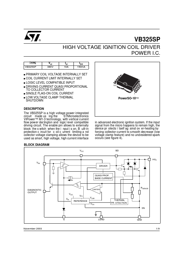
DESCRIPTION
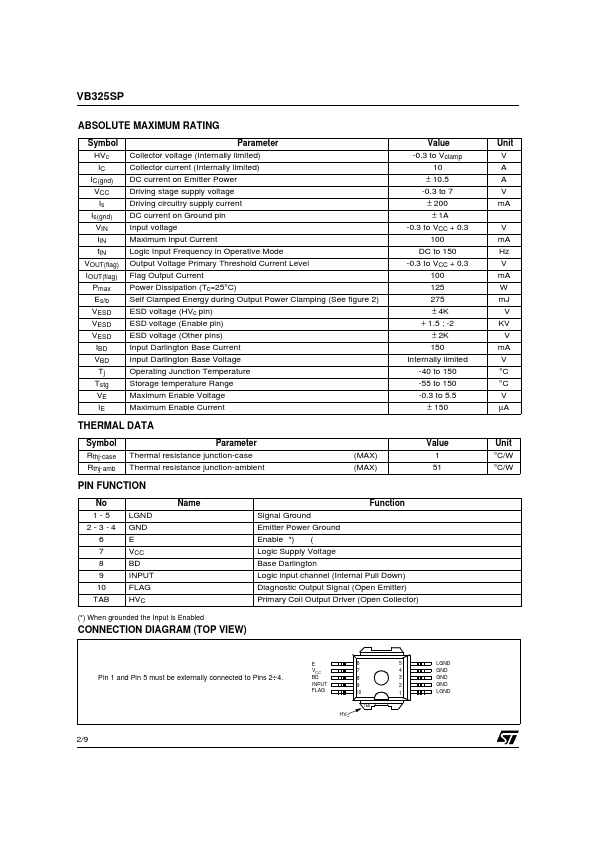
B uilt-in protection c ircuit for c oil c urrent limiting a nd collector voltage clamping allows the device to be used as smart, high voltage, high current interface BLOCK DIAGRAM VCC 10 1 PowerSO-10™ in advanced electronic ignition system. If the input signal from the micro happens to remain high, the device pr otects i tself ag ainst ov er-heating by forcing collector current to s mooth decrease (low voltage clamp feature) and no und esidered spark occurs (see figure 4). BD HVC VIN DRIVER QUASI PROP. BASE CURRENT DIAGNOSTIC OUTPUT VR LIMITER RSENSE VCC VF1 REFERENCE VLIM VTH THERMAL PR OTECTION SN E LGND GND November 2003 1/9 VB325SP ABSOLUTE MAXIMUM RATING Symbol HVc IC IC(gnd) VCC Is Is(gnd) VIN IIN fIN VOUT(flag) IOUT(flag) Pmax Es/b VESD VESD VESD IBD VBD Tj Tstg VE IE Parameter Collector voltage (Internally limited) Collector current (Internally limited) DC current on Emitter Power Driving stage supply voltage Driving circuitry supply current DC current on Ground pin... STMicroelectronics