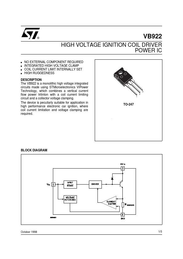
DESCRIPTION
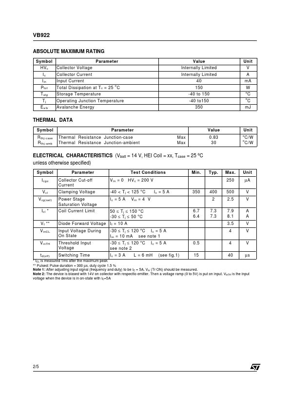
3 2 1 TO-247 BLOCK DIAGRAM October 1998 1/5 VB922 ABSOLUTE MAXIMUM RATING Symbol HVc Ic I in Ptot T stg Tj E s/b Collector Voltage Collector Current Input Current Total Dissipation at T c = 25 o C Storage Temperature Operating Junction Temperature Avalanche Energy Parameter Value Internally Limited Internally Limited 40 150 -40 to 150 -40 to150 350 Unit V A mA W o o C C mJ THERMAL DATA Symbol R thj-case R thj-amb Parameter Thermal Resistance Junction-case Thermal Resistance Junction-ambient Max Max Value 0.83 30 Unit o o C/W C/W ELECTRICAL CHARACTERISTICS
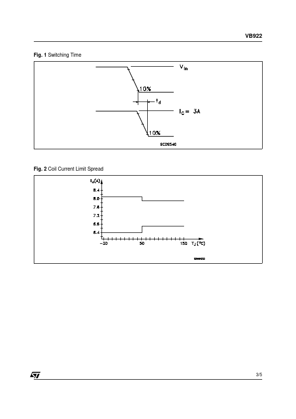
(Vbatt = 14 V, HEI Coil = xx, Tcase = 25 oC unless otherwise specified) Symbol Icgo V cl V cg(sat ) I cl * V f ** V inCL V inTH t d(off) Parameter Collector Cut-off Current Clamping Voltage Power Stage Saturation Voltage Coil Current Limit V in = 0 Test Conditions HV c = 200 V o Min. Typ. Max. 250 Unit µA V V A A V V V µs -40 < T j < 125 C Ic = 5 A Vin = 4 V Ic = 5 A 350 400 2 500 2.5 7.9 8.1 3.5 50 ≤ T j ≤ 150 o C -30 ≤ T... STMicroelectronics