DESCRIPTION
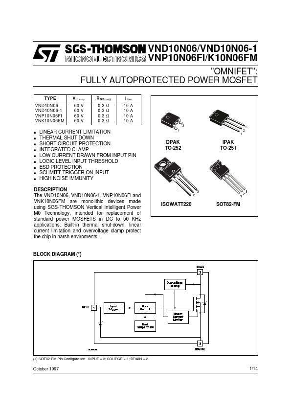
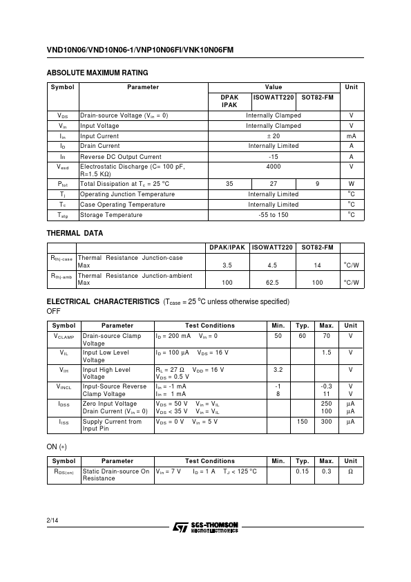
Built-in thermal shut-down, linear current limitation and overvoltage clamp protect the chip in harsh enviroments. 3 1 DPAK TO-252 3 2 1 IPAK TO-251 3 2 1 ISOWATT220 SOT82-FM BLOCK DIAGRAM (*) (∗) SOT82-FM Pin Configuration: INPUT = 3; SOURCE = 1; DRAIN = 2. October 1997 1/14 VND10N06/VND10N06-1/VNP10N06FI/VNK10N06FM ABSOLUTE MAXIMUM RATING Symbol Parameter VDS Vin Iin ID IR Vesd Ptot Tj Tc Tstg Drain-source Voltage (Vin = 0) Input Voltage Input Current Drain Current Reverse DC Output Current Electrostatic Discharge (C= 100 pF, R=1.5 KΩ) Total Dissipation at Tc = 25 oC Operating Junction Temperature Case Operating Temperature Storage Temperature DPAK IPAK Value ISOWATT220 SOT82-FM Internally Clamped Internally Clamped ± 20 Internally Limited -15 4000 Unit V V mA A A V 35 27 9 W Internally Limited oC Internally Limited oC -55 to 150 oC THERMAL DATA Rthj-case Thermal Resistance Junction-case Max Rthj-amb Thermal Resistance Junction-ambient Max DPAK/IPAK ISOWATT220 SOT82-FM 3. STMicroelectronics