Datasheet Details
| Part number | Z00607DA |
|---|---|
| Manufacturer | STMicroelectronics |
| File Size | 64.32 KB |
| Description | SENSITIVE GATE TRIACS |
| Datasheet | Z00607DA_STMicroelectronics.pdf |
|
|
|
Overview: 
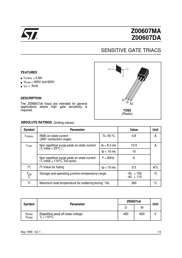
® Z00607MA Z00607DA SENSITIVE GATE TRIACS A2 A1.
| Part number | Z00607DA |
|---|---|
| Manufacturer | STMicroelectronics |
| File Size | 64.32 KB |
| Description | SENSITIVE GATE TRIACS |
| Datasheet | Z00607DA_STMicroelectronics.pdf |
|
|
|
The Z006607xA triacs are intended for general applications where high gate sensitivity is required.
A1 G A2 TO92 (Plastic) ABSOLUTE RATINGS (limiting values) Symbol IT(RMS) ITSM Parameter RMS on-state current (360° conduction angle) Non repetitive surge peak on-state current (Tj initial = 25°C ) Non repetitive surge peak on-state current (Tj initial = 110°C, full cycle) I2t Tstg Tj Tl I2t Value for fusing Tl= 50 °C tp = 8.3 ms tp = 10 ms F = 60Hz tp = 10 ms Value 0.8 10.5 10 8 0.5 - 40, + 150 - 40, + 110 260 A2s °C °C Unit A A Storage and operating junction temperature range Maximum lead temperature for soldering during 10s Symbol VDRM VRRM Parameter Repetitive peak off-state voltage Tj = 110°C Z00607xA D 400 M 600 Unit V May 1999 - Ed: 1 1/4 Z00607DA / Z00607MA THERMAL RESISTANCES Symbol Rth(j-a) Rth(j-l) Junction to ambient Junction to lead Parameter Value 150 60 Unit °C/W °C/W GATE CHARACTERISTICS (maximum values) PG (AV)= 0.1 W PGM = 2 W (tp = 20 µs) ELECTRICAL CHARACTERISTICS Symbol IGT VGT VGD tgt Test Conditions VD=12V (DC) RL=140Ω VD=12V (DC) RL=140Ω VD=VDRM RL=3.3kΩ VD=VDRM IG = 25mA IT = 1.0A dIG/dt = 0.25A/µs IT= 200 mA Gate open IG= 1.2 IGT ITM= 1.1A tp= 380µs VD = VDRM VR = VRRM VD=67%VDRM Gate open (dI/dt)c = 0.35 A/ms Tj= 25°C Tj= 25°C Tj= 110°C Tj= 25°C Tj= 25°C Tj= 25°C Tj= 25°C Tj= 25°C Tj= 110°C Tj= 110°C Tj= 110°C I-III-IV II VTM * IDRM IRRM dV/dt * (dV/dt)c * Quadrant I-II-III IV I-II-III-IV I-II-III-IV I-II-III-IV MAX MAX MAX MIN TYP Sensitivity 07 5 7 1.5 0.2 2 V V µs Unit mA IGM = 1 A (tp = 20 µs) IH * IL MAX MAX MAX MAX MAX MAX MIN MIN 5 10 20 1.5 10 0.1 10 1.5 mA mA V µA mA V/µs V/µs * For either polarity of electrode A2 voltage with reference to electrode A1 Fig 1: Maximum power dissipation versus RMS on-state current.
Fig 2: Correlation between maximum power dissipation and maximum allowable temper
| Brand Logo | Part Number | Description | Manufacturer |
|---|---|---|---|
![]() |
Z00607 | 0.8A TRIAC | Unisonic Technologies |
![]() |
Z00607MA | Triac | NXP |
![]() |
Z00607MA | Sensitive Gate Triacs | HAOPIN |
| Part Number | Description |
|---|---|
| Z00607 | Standard 0.8A Triacs |
| Z00607MA | Standard 0.8A Triacs |
| Z00607MN | Standard 0.8A Triacs |