LB1934T
Overview
- Low voltage drive possible. When using same power supply for V CC and V S : VCC=VS=1.4V min. When using separate power supply for VCC and VS : VS=1.0V min., VCC=1.4V min.
- Low saturation voltage : residual voltage (upper side transistor + lower side transistor) =0.5V typ. at Io=1A.
- Zero power dissipation in standby mode.
- Direct microcontroller drive possible (any strength relationships of voltage supported between microcontroller control signal and VCC or VS).
- Logic power supply and motor power supply can be supplied at separate pins.
- Built-in thermal protection circuit.
- Number of control signals can be optimized for the set. “2-motor control” or “1-motor + 2-load control” can be implemented by 3 control signals. In addition to the above, 4 control signals allow implemention of a “input ignore mode” where two control signals are used in conjunction with other IC input signals.
- Built-in spark killer diode.
- Compact, low-profile package (TSSOP-20 ; thickness=1.1 mm typ.)
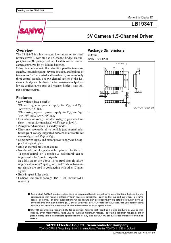
- 65 (0.33) 1