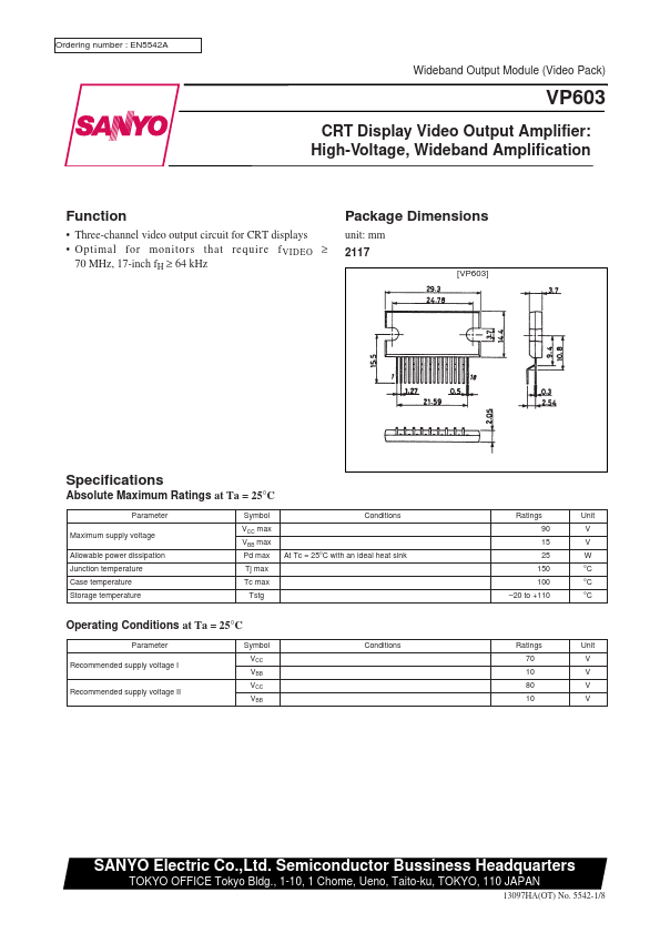
ABSOLUTE MAXIMUM RATINGS
at Ta = 25°C Parameter Maximum supply voltage Allowable power dissipation Junction temperature Case temperature Storage temperature Symbol VCC max VBB max Pd max Tj max Tc max Tstg Conditions At Tc = 25°C with an ideal heat sink Operating Conditions at Ta = 25°C Parameter Recommended supply voltage I Recommended supply voltage II Symbol VCC VBB VCC VBB Conditions Ratings Unit 90 V 15 V 25 W 150 °C 100 °C –20 to +110 °C Ratings Unit 70 V 10 V 80 V 10 V SANYO Electric Co.,Ltd. Semiconductor Bussiness Headquarters TOKYO OFFICE Tokyo Bldg., 1-10, 1 Chome, Ueno, Taito-ku, TOKYO, 110 JAPAN 13097HA(OT) No. 5542-1/8 VP603 ELECTRICAL CHARACTERISTICS
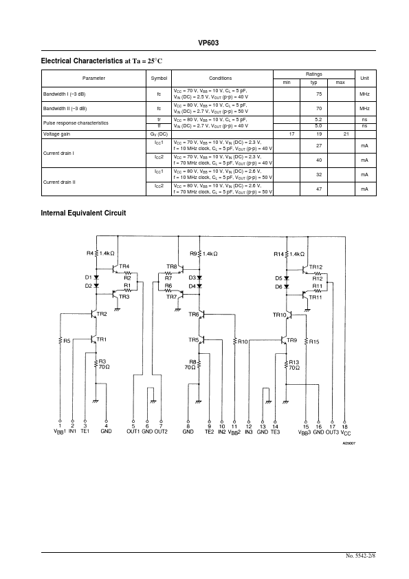
at Ta = 25°C Parameter Bandwidth I (–3 dB) Bandwidth II (–3 dB) Pulse response characteristics Voltage gain Current drain I Current drain II Symbol Conditions fc fc tr tf GV (DC) ICC1 ICC2 ICC1 ICC2 VCC = 70 V, VBB = 10 V, CL = 5 pF, VIN (DC) = 2.5 V, VOUT (p-p) = 40 V VCC = 80 V, VBB = 10 V, CL = 5 pF, VIN (DC) = 2.7 V, VOU... Sanyo Electric