Sanyo Electric VPS13
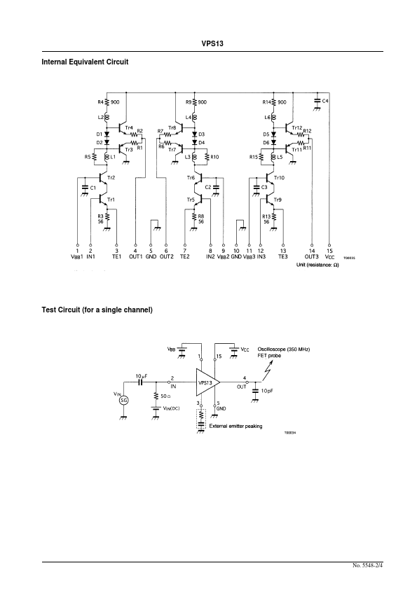
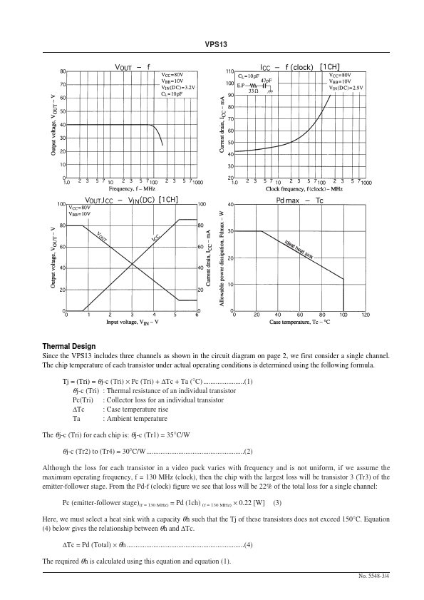
the VPS13 includes three channels as shown in the circuit diagram on page 2, we first consider a single channel. The chip temperature of each transistor under actual operating conditions is determined using the following formula.| Part No. | VPS13 |
|---|---|
| Datasheet | VPS13 Download |
| Manufacturer |  Sanyo Electric |
| Description | CRT Display Video Output Amplifier/ High-Voltage/Wideband Amplifier |
| Buy | Stock & Price |
FEATURES
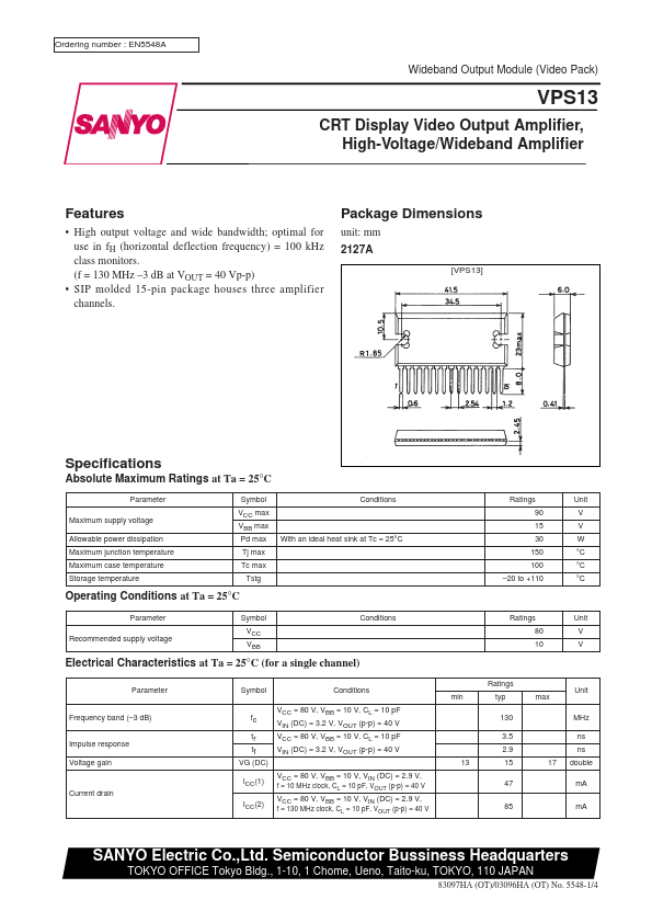
● High output voltage and wide bandwidth; optimal for use in fH (horizontal deflection frequency) = 100 kHz class monitors. (f = 130 MHz –3 dB at VOUT = 40 Vp-p)● SIP molded 15-pin package houses three amplifier channels. Package Dimensions unit: mm 2127A [VPS13] Specifications
ABSOLUTE MAXIMUM RATINGS
at Ta = 25°C Parameter Maximum supply voltage Allowable power dissipation Maximum junction temperature Maximum case temperature Storage temperature Symbol VCC max VBB max Pd max Tj max Tc max Tstg With an ideal heat sink at Tc = 25°C Conditions Ratings 90 15 30 150 100 –20 to +110 Unit V V W °C °C °C Operating Conditions at Ta = 25°C Parameter Recommended supply voltage Symbol VCC VBB Conditions Ratings 80 10 Unit V VELECTRICAL CHARACTERISTICS
at Ta = 25°C (for a single channel) Parameter Symbol Conditions VCC = 80 V, VBB = 10 V, CL = 10 pF VIN (DC) = 3.2 V, VOUT (p-p) = 40 V VCC = 80 V, VBB = 10 V, CL = 10 pF VIN (DC) = 3.2 V, VOUT (p-p) = 40 V 13 VCC = 80 V, VBB = 10 V, VIN...