SemiHow HRLF125N06K
N-Channel MOSFET
| Part No. | HRLF125N06K |
|---|---|
| Datasheet | HRLF125N06K Download |
| Manufacturer |  SemiHow |
| Description | N-Channel MOSFET |
| Buy | Stock & Price |
FEATURES
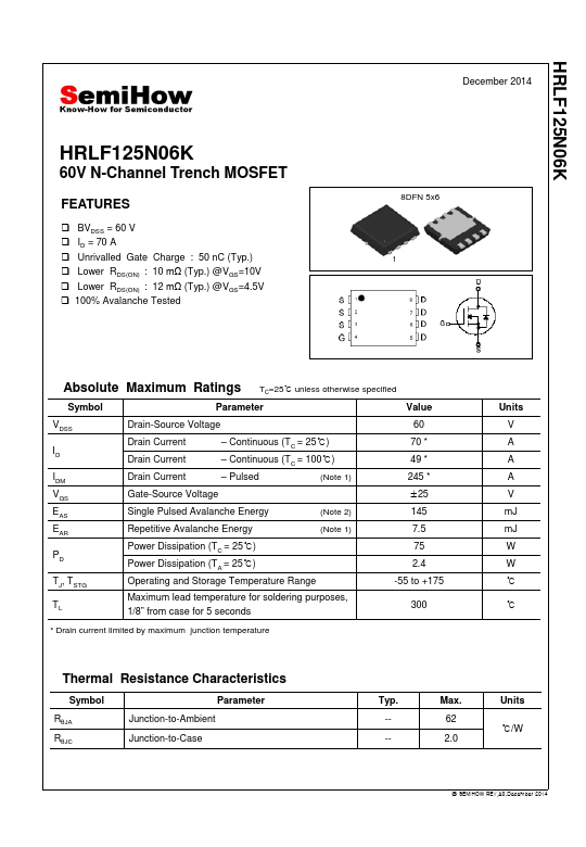
● BVDSS = 60 V● ID = 70 A
● Unrivalled Gate Charge : 50 nC (Typ.)
● Lower RDS(ON) : 10 mΩ (Typ.) @VGS=10V
● Lower RDS(ON) : 12 mΩ (Typ.) @VGS=4.5V
● 100% Avalanche Tested December 2014 8DFN 5x6 1
ABSOLUTE MAXIMUM RATINGS
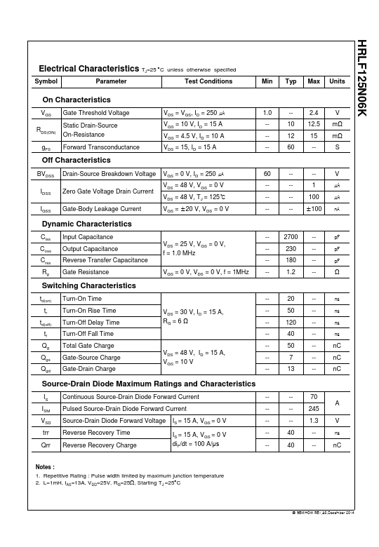
TC=25℃ unless otherwise specified Symbol Parameter Value VDSS ID IDM VGS EAS EAR PD TJ, TSTG TL Drain-Source Voltage Drain Current Drain Current Drain Current – Continuous (TC = 25℃) – Continuous (TC = 100℃) – Pulsed (Note 1) Gate-Source Voltage Single Pulsed Avalanche Energy (Note 2) Repetitive Avalanche Energy (Note 1) Power Dissipation (TC = 25℃) Power Dissipation (TA = 25℃) Operating and Storage Temperature Range Maximum lead temperature for soldering purposes, 1/8” from case for 5 seconds 60 70 * 49 * 245 * ±25 145 7.5 75 2.4 -55 to +175 300 * Drain current limited by maximum junction temperature Units V A A A V mJ mJ W W ℃ ℃ Thermal Resistance Characteristics Symbol Parameter RθJA RθJC Junction-to-Ambient Junction-to-Case Typ. --- Max. 62 2.0 Units ℃/W...