GL561
Overview
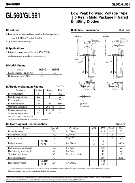
- Low peak forward voltage suitable for battery drive ( VFM : TYP.1.7V at I FM : 0.5A) 2. φ 5 resin mold package Low Peak Forward Voltage Type φ 5 Resin Mold Package Infrared Emitting Diodes s Outline Dimensions GL560 Protruded resin 1.5MAX Colorless 0.15 transparent φ 5+ - 0.15 resin 7.3 ± 0.2 0.8 ± 0.2 (Unit : mm) GL561 Protruded resin 1.5MAX
- 15 φ 5+ - 0.15 Colorless transparent resin
- Infrared remote controllers for TVs, VCRs, audio equipment and air conditioners Notch 23.5 ± 1 0.5 ± 0.1 0.5 ± 0.1 23.5 ± 1 1 (2.54 ) 0.5 ± 0.1 s Model Lineup Model Radiant intensity TYP. (mW/sr) Half intensity angle TYP. ( ˚ ) GL560 14 ± 21 GL561 25 ± 13
- 5 ± 0.1 2 1
- 3MIN 2 (2.54 ) 0.8 5.8 ± 0.2 s Absolute Maximum Ratings Parameter Forward current Peak forward current Reverse voltage Power dissipation Operating temperature Storage temperature Soldering temperature Symbol IF I FM VR P Topr Tstg Tsol Rating 100 1 6 150 - 25 to + 85 - 40 to + 85 260 (Ta=25˚C) Unit mA A V mW ˚C ˚C ˚C
- 1 2 1 1 Anode 2 Cathode
- 1 Pulse width <=100µ s, Duty ratio=0.01 *2 For 10 seconds at the position of 2.6 mm from the resin edge s Electro-optical Characteristics Parameter Forward voltage Peak forward voltage Reverse current
- 3 (Ta=25 ˚C) Symbol VF V FM IR Conditions I F = 50mA I FM = 0.5A V R = 3V I F = 50mA I F = 5mA I F = 5mA V R = 0, f = 1MHz IF = 20mA MIN. 5 12 TYP. 1.25 1.7 14 25 940 45 50 300 ± 21 ± 13 MAX. 1.37 2.5 10 Unit V V µA mW/sr nm nm pF kHz ˚ ˚ Radiant intensity Peak emission wavelength Half intensity wavelength Terminal capacitance Response frequency Half intensity angle