LT135
Overview
- 7±0.3
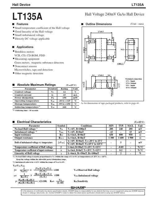
- 4 0.6 (Unit : mm) 1 4
- 9±0.2 1.9 (0.85) N 2
- 4 (0.95) 4-R0.2
- 5±0.2
- 3 (Ta=25˚C) Unit V mA mW ˚C ˚C ˚C Parameter Control voltage Control current Power dissipation Operating temperature Storage temperature Soldering temperature*1
- 1 Soldering time : 10 seconds Symbol Rating VC 12 IC 15 150 PD -20 to +125 Topr -55 to +150 Tstg 260 Tsol As for dimensions of tape-packaged products, refer to page 44 . s Electrical Characteristics Parameter No-load Hall voltage *1 Imbalanced voltage *2 Input resistance Output resistance Drift of imbalanced voltage vs. temperature Temperature coefficient of Hall voltage Temperature coefficient of input resistance Linearity of Hall voltage Symbol VH VHO RIN ROUT |∆VHO| β α γ Conditions VC=6V, B=100mT VC=6V, B=0mT IM=1mA, B=0mT IM=1mA, B=0mT VC=6V, B=0mT, Ta=-20˚C to 25˚C VC=6V, B=0mT, Ta=25˚C to 125˚C IC=6mA, B=100mT, T1=-20˚C, T2=125˚C IM=1mA, B=0mT, T1=-20˚C, T2=125˚C IC=6mA, B1=50mT, B2=100mT MIN 200 -15 650 1 300 TYP. 240 800 1 600 5 -0.03 0.2 2 MAX. 280 15 950 1 900 - (0to0.15)
- 8 s Absolute Maximum Ratings Terminal connection 1:VC Input 2:VH Output 3:VC Input 4:VH Output
- 16+0.10 -0.06
- 1 +0.2 -0.1 (Ta=25˚C) Unit mV mV Ω Ω mV %/˚C %/˚C %