DESCRIPTION
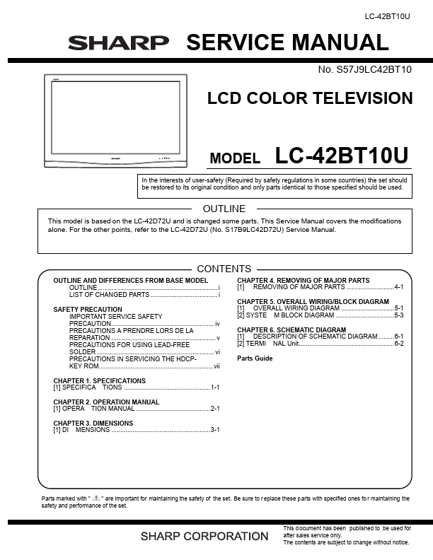
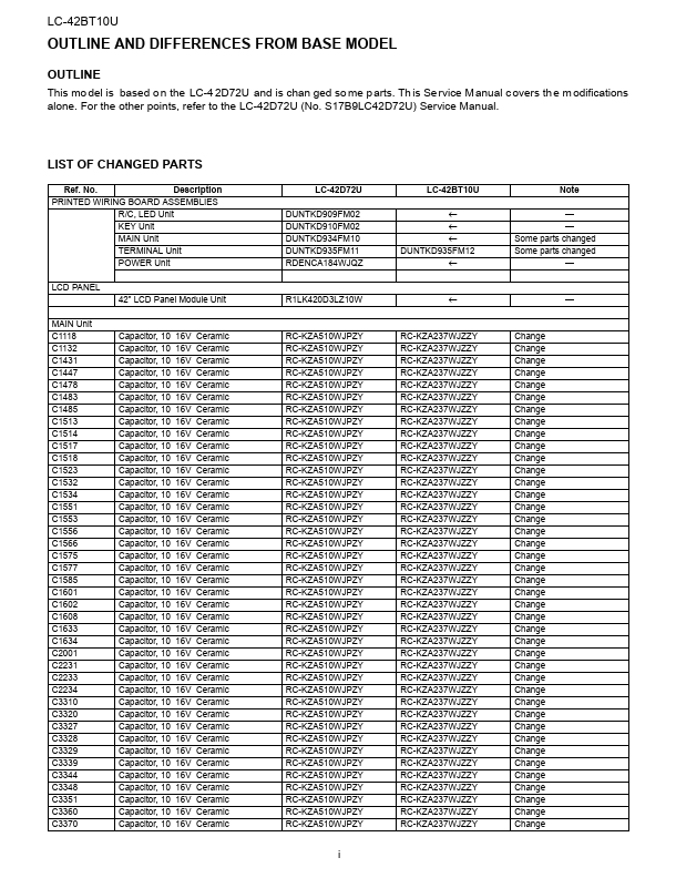
OF SCHEMATIC DIAGRAM .........6-1 [2] TERMI NAL Unit......................................................6-2 Parts Guide Parts marked with " " are important for maintaining the safety of the set. Be sure to r eplace these parts with specified ones fo r maintaining the safety and performance of the set. This d ocument has been published to be used for after sales service only. The contents are subject to change without notice. LC-42BT10U LC-42BT10U Service Manual OUTLINE AND DIFFERENCES FROM BASE MODEL OUTLINE This mo del is based o n the LC-4 2D72U and is chan ged so me p arts. Th is Se rvice M anual c overs th e m odifications alone. For the other points, refer to the LC-42D72U (No. S17B9LC42D72U) Service Manual. LIST OF CHANGED PARTS Ref. No. DESCRIPTION
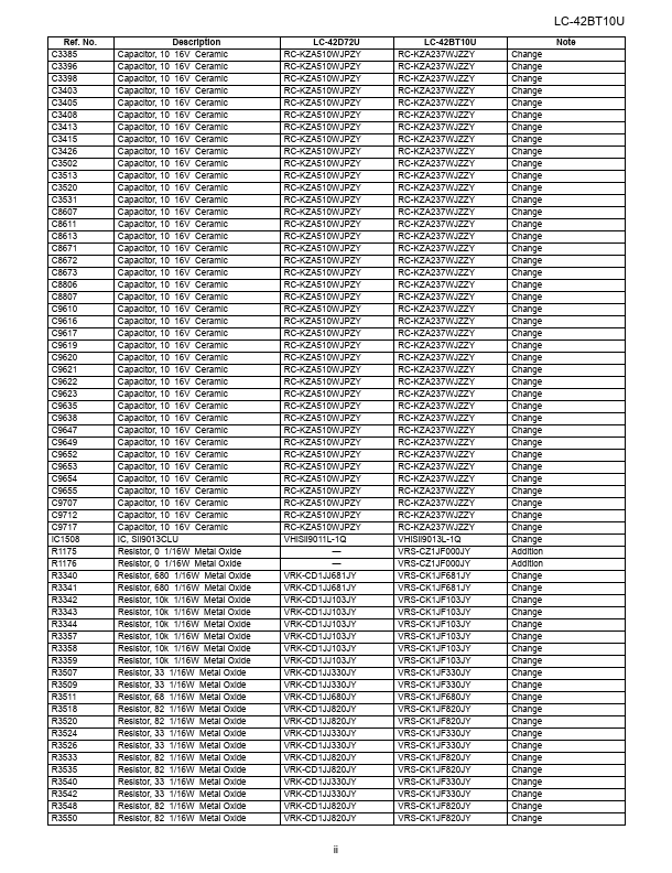
PRINTED WIRING BOARD ASSEMBLIES R/C, LED Unit KEY Unit MAIN Unit TERMINAL Unit POWER Unit LCD PANEL 42” LCD Panel Module Unit MAIN Unit C1118 C1132 C1431 C1447 C1478 C1483 C1485 C1513 C1514 C1517 C1518 C1523 C1532 C1534... Sharp