PQ05RF14
Overview
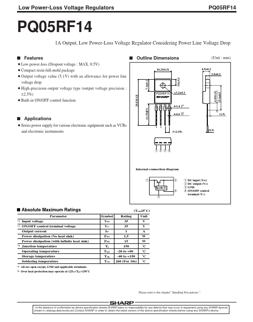
- 2MAX 3.6±0.2 4.5±0.2 (Unit : mm)
- 8±0.2 7.4±0.2
- 1MAX PQ05RF14 4-1.4 13.5MIN 4-0.6 +0.3 -0 +0.2 -0.1 s Applications ¡Series power supply for various electronic equipment such as VCRs and electronic instruments 3-(2.54) (0.5) 1 q 2 q 3 q 4 q Internal connection diagram 1 Specific IC 4 3 2 1 DC input (VIN) 2 DC output (VO) 3 GND 4 ON/OFF control terminal (VC) s Absolute Maximum Ratings Parameter
- 1 *1 (Ta=25˚C) Symbol Rating Unit VIN 35 V VC 35 V IO 1 A PD1 1.5 W PD2 15 W Tj 150 ˚C Topr -20 to +80 ˚C Tstg -40 to +150 ˚C Tsol 260 (For 10s) ˚C
- 2 Input voltage ON/OFF control terminal voltage Output current Power dissipation (No heat sink) Power dissipation (with infinite heat sink) Junction temperature Operating temperature Storage temperature Soldering temperature All are open except, GND and applicable terminals. Over heat protection may operate at 125=<Tj=<150˚C
- Please refer to the chapter“ Handling Precautions ”. “ In the absence of confirmation by device specification sheets,SHARP takes no responsibility for any defects that may occur in equipment using any SHARP devices shown in catalogs,data books, SHARP in order to obtain the latest version of the device specification sheets before using any SHARP's device. ”
- 8MAX 15.6±0.5 (1.5) φ3.2±0.1 Low Power-Loss Voltage Regulators s Electrical Characteristics Parameter Output voltage Load regulation Line regulation Temperature coefficient of output voltage Ripple rejection Dropout voltage ON-state voltage for control ON-state