MBRB2045CT
MBRB2045CT is 20A Dual Schottky Rectifiers manufactured by Silicon Standard.
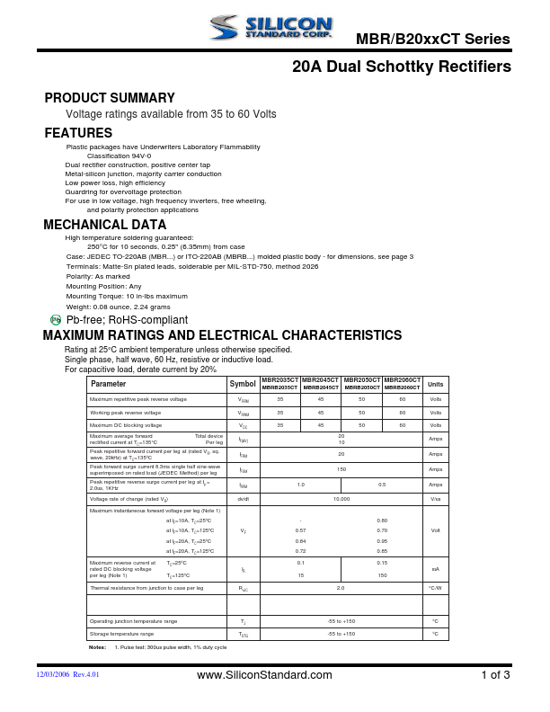
FEATURES
Plastic packages have Underwriters Laboratory Flammability Classification 94V-0
Dual rectifier construction, positive center tap Metal-silicon junction, majority carrier conduction Low power loss, high efficiency Guardring for overvoltage protection For use in low voltage, high frequency inverters, free wheeling, and polarity protection applications
MECHANICAL DATA
High temperature soldering guaranteed: 250°C for 10 seconds, 0.25" (6.35mm) from case
Case: JEDEC TO-220AB (MBR...) or ITO-220AB (MBRB...) molded plastic body
- for dimensions, see page 3 Terminals: Matte-Sn plated leads, solderable per MIL-STD-750, method 2026 Polarity: As marked Mounting Position: Any Mounting Torque: 10 in-lbs maximum
Weight: 0.08 ounce, 2.24 grams
Pb-free; Ro HS-pliant
MAXIMUM RATINGS AND ELECTRICAL CHARACTERISTICS
Rating at 25°C ambient temperature unless otherwise specified. Single phase, half wave, 60 Hz, resistive or inductive load.
For capacitive load, derate current by 20%
Parameter
Symbol
MBR2035CT MBR2045CT MBRB2035CT MBRB2045CT
MBR2050CT MBR2060CT MBRB2050CT MBRB2060CT
Units
Maximum repetitive peak reverse voltage
Working peak reverse voltage
Maximum DC blocking voltage
Maximum average forward
Total device rectified current at TC=135°C
Per leg
Peak repetitive forward current per leg at (rated V , sq. R wave, 20k Hz) at TC=135o C
Peak forward surge current 8.3ms single half sine-wave superimposed on rated load (JEDEC Method) per leg
Peak repetitive reverse surge current per leg at tp = 2.0us, 1KHz
Voltage rate of change (rated V ) R
Maximum instantaneous forward voltage per leg (Note 1)
Maximum reverse current at rated DC blocking voltage per leg (Note 1) at IF=10A, TC=25o C at IF=10A, TC=125o C at IF=20A, TC=25o C at IF=20A, TC=125o C TC=25o C
TC=125o C
Thermal resistance from junction to case per leg
VRRM VRWM VDC IF(AV) IFRM IFSM IRRM dv/dt
RθJC
35 45 50 60 35 45 50 60 35 45 50 60
20 10 20
1.0...