Datasheet Summary
..
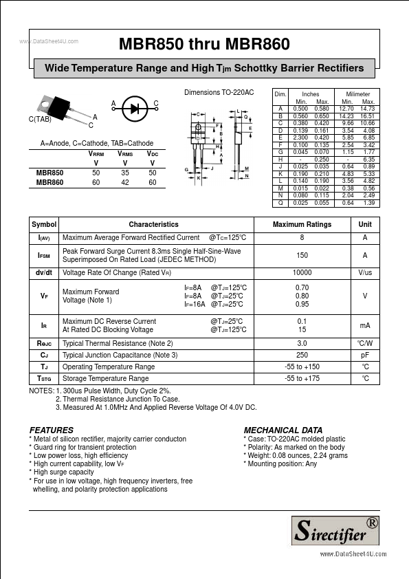
MBR850 thru MBR860
Dimensions TO-220AC A C
Dim. A B C D E F G H J K L M N Q Inches Min. Max. 0.500 0.580 0.560 0.650 0.380 0.420 0.139 0.161 2.300 0.420 0.100 0.135 0.045 0.070 0.250 0.025 0.035 0.190 0.210 0.140 0.190 0.015 0.022 0.080 0.115 0.025 0.055 Milimeter Min. Max. 12.70 14.73 14.23 16.51 9.66 10.66 3.54 4.08 5.85 6.85 2.54 3.42 1.15 1.77 6.35 0.64 0.89 4.83 5.33 3.56 4.82 0.38 0.56 2.04 2.49 0.64 1.39
Wide Temperature Range and High Tjm Schottky Barrier Rectifiers
C(TAB)
A=Anode, C=Cathode, TAB=Cathode VRRM V 50 60 VRMS V 35 42 VDC V 50 60
MBR850 MBR860
Symbol I(AV) IFSM dv/dt VF
Characteristics Maximum Average Forward Rectified Current...