MBR2030CT
| Part Number | Manufacturer | Description |
|---|---|---|
| MBR2030CTL | onsemi | Dual Schottky Power Rectifier |
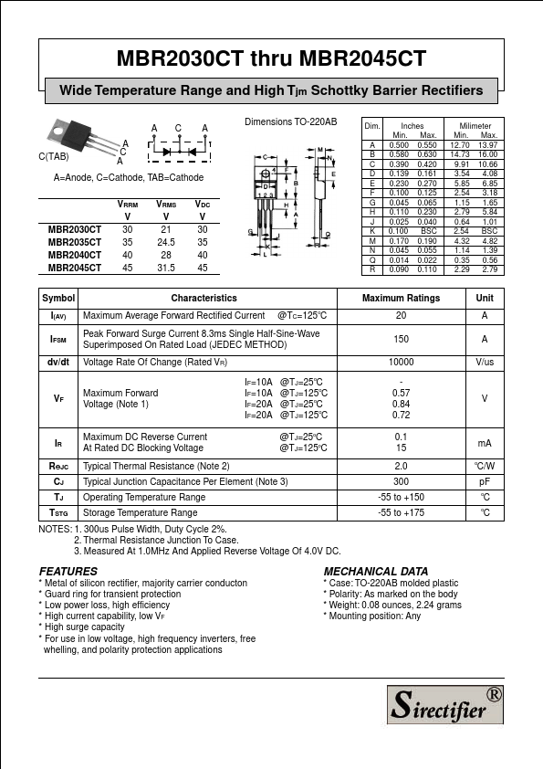
| MBR2030CT | Mospec Semiconductor | Schottky Barrier Rectifiers |
| MBR2030CTLG | onsemi | Dual Schottky Power Rectifier |
| MBR2030CTL | Inchange Semiconductor | Schottky Barrier Rectifier |
| MBR2030CT | Micro Commercial Components | 20 Amp Schottky Barrier Rectifier |
| MBR2030CTL | Digitron Semiconductors | 20A SCHOTTKY RECTIFIERS |
| MBR2030CT | Taitron Components | 20A Schottky Barrier Rectifiers |
| MBR2030CT | KD | SCHOTTKY BARRIER RECTIFIER |
| MBR2030C | Eris Technology | Schottky Barrier Rectifiers |
| MBR2030 | Inchange Semiconductor | Schottky Barrier Rectifier |