Solutions Cubed AN603
The first option is to increase the power dissipating capability of your system. This can most easily be accomplished by increasing the forced airflow over the ICON H-Bridge with a highspeed, high-volume, fan.| Part No. | AN603 |
|---|---|
| Datasheet | AN603 Download |
| Manufacturer | Solutions Cubed |
| Description | Operating ICON H-Bridges in Parallel |
| Buy | Stock & Price |
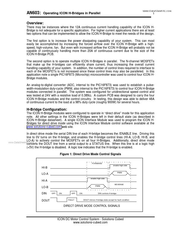
AN603: Operating ICON H-Bridges in Parallel 1 Overview: There may be instances where the 12A continuous current handling capability of the ICON HBridge is not adequate for a specific application. For higher current applications there are at least two options that can be implemented to allow the ICON H-Bridge to meet the needs of the design. But even with increased airflow the ICON H-Bridge will probably not be capable of continuously handling more than 20A of continuous current due to the size of the ICON H-Bridge PCB. The second option is to operate multiple ICON H-Bridges in parallel. The N-channel MOSFETs that make up the H-bridges can efficiently share current, thus increasing the overall current handling capability of your system. In addition, the number of control lines required to interface to each of the MOSFETs is not increased since these control lines may also be paralleled. In this application note a single PIC16F873 (Microchip) microcontroller was used to control four ICON HBridge modules.