D2SB20
D2SB20 is SINGLE-PHASE BRIDGE RECTIFIER manufactured by Sunmate.
- Part of the D2SB05 comparator family.
- Part of the D2SB05 comparator family.
D2SB05-D2SB80
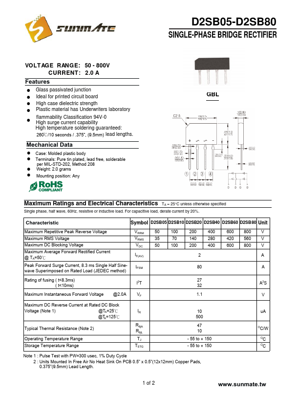
SINGLE-PHASE BRIDGE RECTIFIER
VOLTAGE RANGE: 50
- 8 00V
CURRENT: 2.0 A
Features
! Glass passivated junction
! Ideal for printed circuit board
! High case dielectric strength
! Plastic material has Underwriters laboratory
! flammability Classification 94V-0 High surge current capability
High temperature soldering guaranteed:
260℃/10 seconds / .375", (9.5mm) lead lengths.
Mechanical Data
! Case: Molded plastic body ! Terminals: Pure tin plated, lead free, solderable per MIL-STD-202, Method 208
! Weight: 2.0 grams ! Mounting position: Any
Maximum Ratings and Electrical Characteristics TA = 25°C unless otherwise specified
Single phase, half wave, 60Hz, resistive...