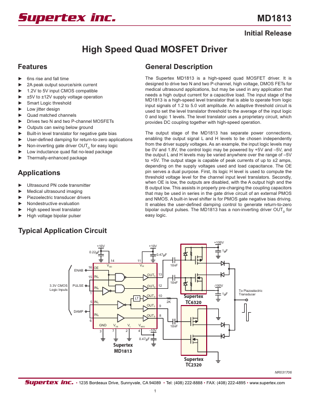
MD1813
MD1813 is HIGH SPEED QUAD MOSFET DRIVER manufactured by Supertex.
Features
- -
- -
- -
- -
- -
- -
- - 6ns rise and fall time 2A peak output source/sink current 1.2V to 5V input CMOS patible ±5V to ±12V supply voltage operation Smart Logic threshold Low jitter design Quad matched channels Drives two N and two P-channel MOSFETs Outputs can swing below ground Built-in level translator for negative gate bias User-defined damping for return-to-zero applications Non-inverting gate driver OUTD for easy logic Low inductance quad flat no-lead package Thermally-enhanced package
Initial Release
General Description
The Supertex MD1813 is a high-speed quad MOSFET driver. It is designed to drive two N and two P-channel, high voltage, DMOS FETs for medical ultrasound applications, but may be used in any application that needs a high output current for a capacitive load. The input stage of the MD1813 is a high-speed level translator that is able to operate from logic input signals of 1.2 to 5.0 volt amplitude. An adaptive threshold circuit is used to set the level translator threshold to the average of the input logic 0 and logic 1 levels. The level translator uses a proprietary circuit, which provides DC coupling together with high-speed operation. The output stage of the MD1813 has separate power connections, enabling the output signal L and H levels to be chosen independently from the driver supply voltages. As an example, the input logic levels may be 0V and 1.8V, the control logic may be powered by +5V and
- 5V, and the output L and H levels may be varied anywhere over the range of
- 5V to +5V. The output stage is capable of peak currents of up to ±2 amps, depending on the supply voltages used and load capacitance. The OE pin serves a dual purpose. First, its logic H level is used to pute the threshold voltage level for the channel input level translators. Secondly, when OE is low, the outputs are disabled, with the A output high and the B output low. This assists in properly pre-charging the coupling capacitors that may be used in...