TEA1007
TEA1007 is Simple Phase Controller manufactured by TEMIC Semiconductors.
Adronic ponents Gmb H
Simple Phase Control Circuit
Description
Integrated circuit, TEA1007, is designed as a general phase control circuit in bipolar technology. It has an internal supply voltage limitation. With typical 150 m A ignition pulse, it is possible to determine the phase-shift of the ignition point by paring the mains sync. ramp voltage with a preset required value. It generates a single ignition pulse per half wave; therefore, it is suitable for capacitive and inductive loads in low cost applications.
Features v D Current consumption 2.5 m A
D Ignition pulse typ. 150 m A D Voltage and current synchronization
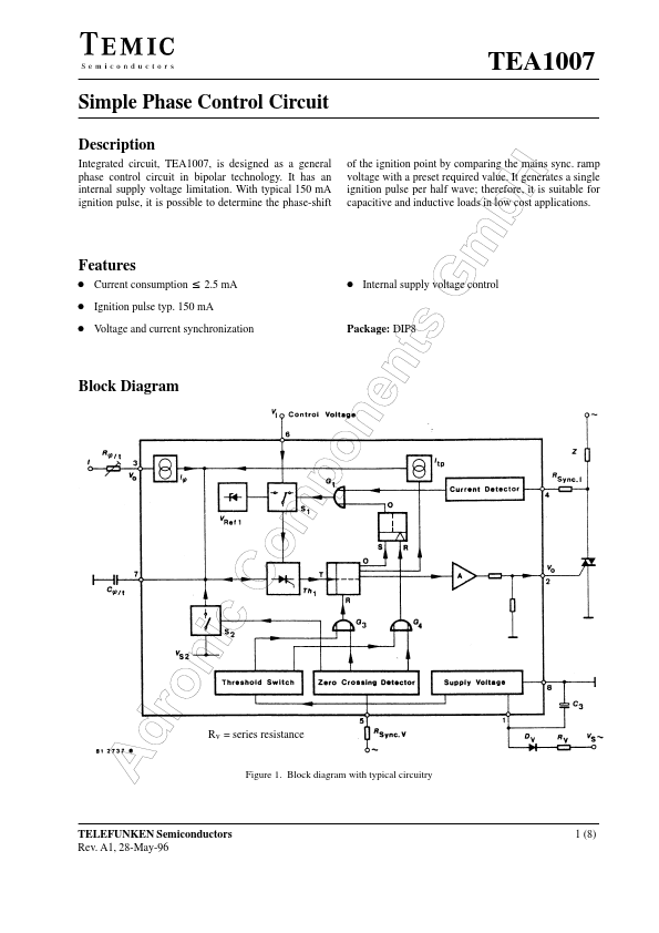
Block Diagram
D Internal supply voltage control
Package: DIP8
Rv = series resistance Figure 1. Block diagram with typical circuitry
TELEFUNKEN Semiconductors Rev. A1, 28-May-96
1 (8)
Adronic ponents Gmb H
General Description
The phase-shift of the ignition point is determined in the usual manner by parison between a mains synchronized ramp voltage and a predetermined required value. The capacitor Cö/t between Pin 7 and the mon reference point Pin 8 is discharged at the zero transition of the mains voltage via the Vo detector, gate G2 and switch S2. After the end of the zero transition pulse, Cö/t is charged from the constant current source Iö, whose value is adjusted externally with Rö at Pin 3 due to the unavoidable tolerance of Cö/t (Phase 1).
When the potential at Pin 7 reaches the nominal value predetermined at Pin 6, the thyristor Th1, which also functions as a parator, ignites and sets the following clock flip-flop. The output of the clock flip-flop releases the output amplifier, connects a second constant current source to the capacitor Cö/t, and switches the reference voltage switch S1 to an internally generated threshold voltage VRef1 via an RS flip-flop and the OR gate G1.
The capacitor Cö/t is charged in this second phase by Iö + Itp until it reaches the internal reference voltage VRef. The length...