DESCRIPTION
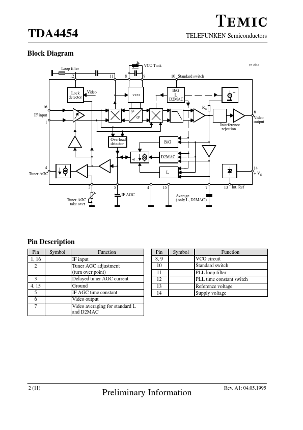
The phase detector compares the phase of IF signal (0°) with the output signal of the VCO (90°) and sets the VCO frequency accordingly. A lock detector switches the PLL loop filter according to the state of the PLL (locked-PLL slow, unlocked-PLL fast). A second output of the VCO (0°) provides the reference carrier for the video demodulator. The polarity of the demodulator can be inverted by the standard switch (Pin 10), so that negative or positive modulated IF signals are always available with the same polarity at the demodulator output. The demodulated video signal is filtered, amplified and fed via an interference limiter to the video output (Pin 6). The standard switch also determines the clamp level of the video amplifier and the required IF-AGC mode. In the standard B/G mode the sync peak value is the criterion for a fast charge and discharge. In the standard L mode on the other hand, fast AGC action is achieved by charging at peak white level and discharging by the averaged video signal (time constant on Pin 7). TEMIC Semiconductors