FEATURES
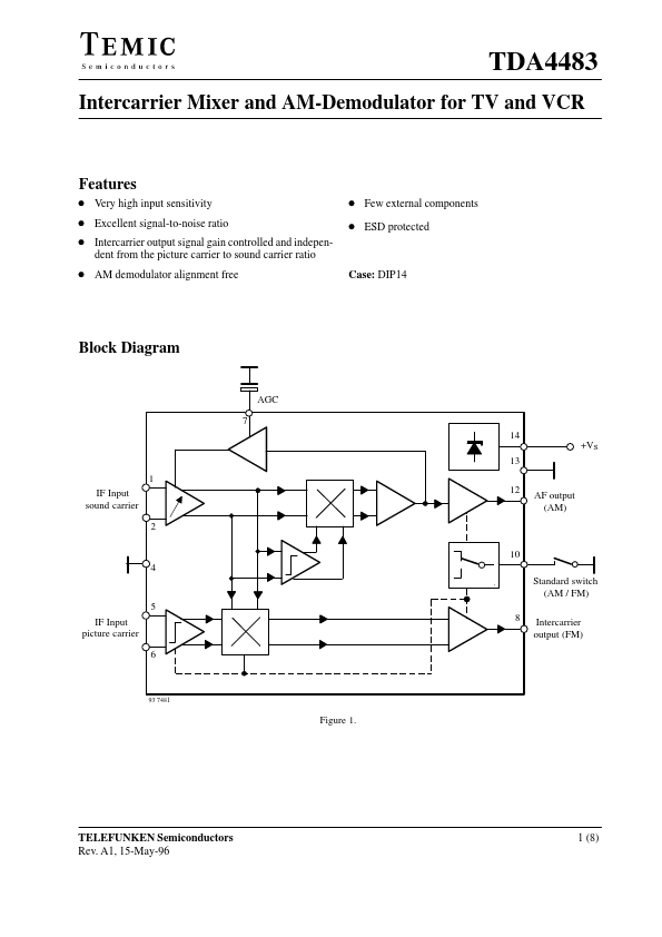
D Very high input sensitivity D Excellent signal-to-noise ratio D Intercarrier output signal gain controlled and independent from the picture carrier to sound carrier ratio D Few external components D ESD protected D AM demodulator alignment free Case: DIP14 Block Diagram AGC 7 14 +VS 13 1 IF Input sound carrier 2 10 4 Standard switch (AM / FM) 5 IF Input picture carrier 6 8 Intercarrier output (FM) 12 AF output (AM) 93 7481 Figure 1. TELEFUNKEN Semiconductors Rev. A1, 15-May-96 1 (8) TDA4483 Pin DESCRIPTION
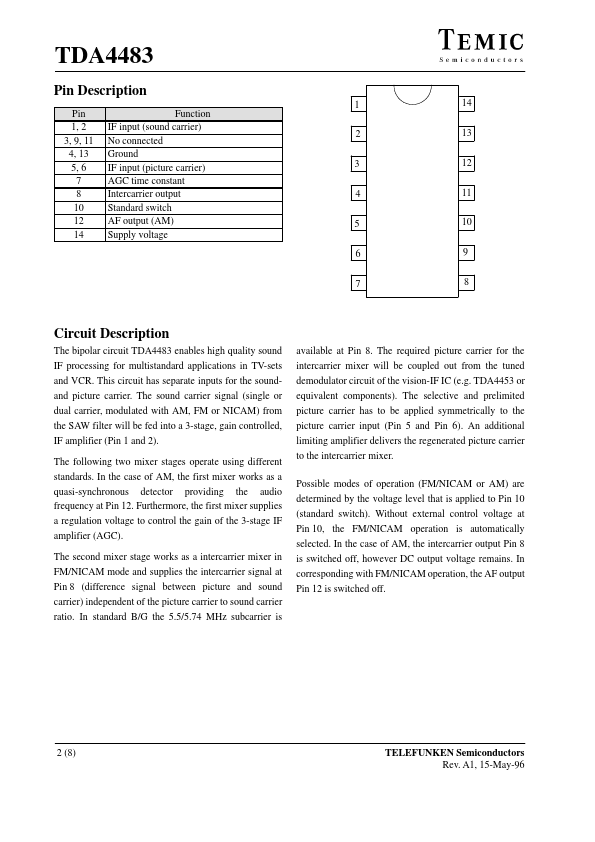
1 Pin 1, 2 3, 9, 11 4, 13 5, 6 7 8 10 12 14 Function IF input (sound carrier) No connected Ground IF input (picture carrier) AGC time constant Intercarrier output Standard switch AF output (AM) Supply voltage 2 3 4 5 6 7 14 13 12 11 10 9 8 Circuit DESCRIPTION
The sound carrier signal (single or dual carrier, modulated with AM, FM or NICAM) from the SAW filter will be fed into a 3-stage, gain controlled, IF amplifier (Pin 1 and 2). The following two mixer stages operate using different standards. TEMIC Semiconductors