DESCRIPTION
FEATURES
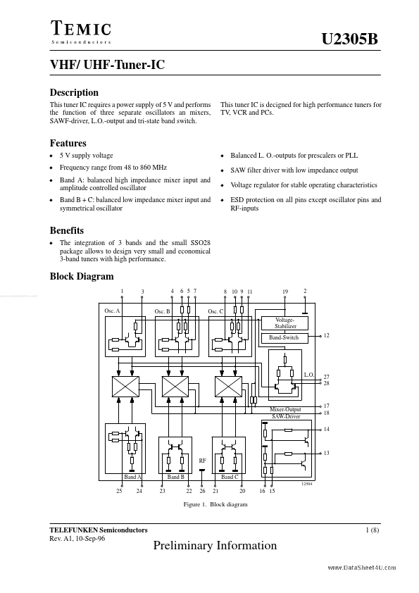
D 5 V supply voltage D Frequency range from 48 to 860 MHz D Band A: balanced high impedance mixer input and amplitude controlled oscillator D Band B + C: balanced low impedance mixer input and symmetrical oscillator D Balanced L. O.-outputs for prescalers or PLL D SAW filter driver with low impedance output D Voltage regulator for stable operating characteristics D ESD protection on all pins except oscillator pins and RF-inputs Benefits D The integration of 3 bands and the small SSO28 package allows to design very small and economical 3-band tuners with high performance. Block Diagram 1 3 4 6 5 7 8 10 9 11 19 2 Osc. A Osc. B Osc. C VoltageStabilizer Band-Switch 12 L.O. 27 28 Mixer-Output SAW-Driver 17 18 14 13 RF Band A 25 24 23 Band B 22 26 21 Band C 12504 20 16 15 Figure 1. Block diagram TELEFUNKEN Semiconductors Rev. A1, 10-Sep-96 1 (8) Preliminary Information U2305B Pin DESCRIPTION
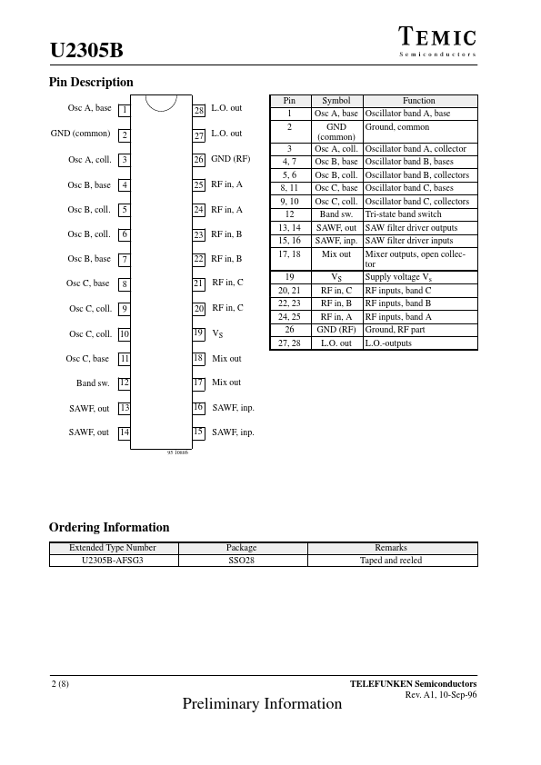
Osc A, base GND (common) Osc A, coll. Osc B, base Osc B, coll. Osc B, coll. Osc B, base Osc C, base Osc C, coll. TEMIC Semiconductors