FEATURES
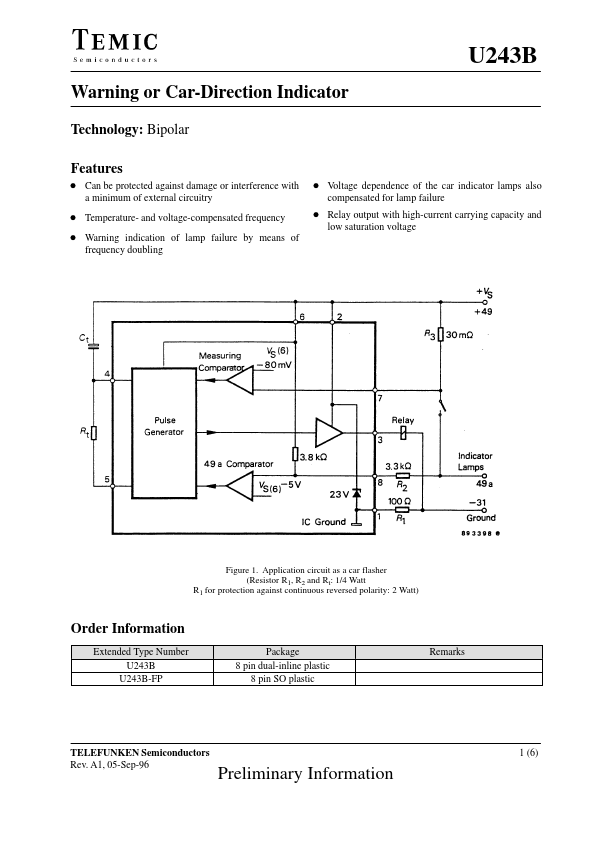
D Can be protected against damage or interference with a minimum of external circuitry D Voltage dependence of the car indicator lamps also compensated for lamp failure D Temperature- and voltage-compensated frequency D Warning indication of lamp failure by means of frequency doubling D Relay output with high-current carrying capacity and low saturation voltage Figure 1. Application circuit as a car flasher (Resistor R1, R2 and Rt: 1/4 Watt R1 for protection against continuous reversed polarity: 2 Watt) Order Information Extended Type Number U243B U243B-FP Package 8 pin dual-inline plastic 8 pin SO plastic Remarks TELEFUNKEN Semiconductors Rev. A1, 05-Sep-96 1 (6) Preliminary Information U243B Circuit DESCRIPTION
The application circuit shows the operation of 1 Rt Ct 1.5 (Hz) where f1 is the frequency in normal flashing operation (basic frequency). The control frequency f2 is typically 2.2 times the value of f1 and is the frequency in the case of lamp failure. The bright periods for f1 and f2 are internally set in the IC and are 50% for f1 and 40% for f2. TEMIC Semiconductors