Datasheet4U.com
🌙
LM6060 Datasheet | TOPWAY
Part:
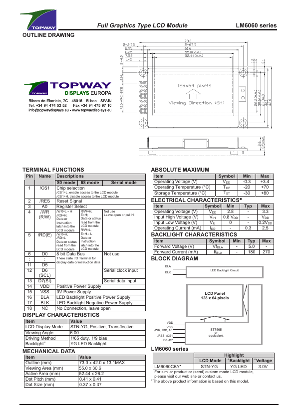
LM6060
Description:
Full Graphics Type LCD Module
Manufacturer:
TOPWAY
Size:
78.31 KB
LM6060 Datasheet (PDF) Download
Related LM6060 Datasheets
LM6060CFW LCD Module User Manual
LM6060CFW-3 LCD Module User Manual
LM6060CCW-3 LCD Module User Manual
LM6060CCW-2 LCD Module User Manual
LM6060CFW-4 LCD Module User Manual
TOPWAY
LM6060
Key Features
5.0 - 180 270
Datasheets by Manufacturer
Part Number
Manufacturer
Description
LM6063SYR
Goldentek Display
Display
×
Close