FGA10
FGA10 is Photodiodes manufactured by Thorlabs.
435 Route 206
- P.O. Box 366 Newton, NJ 07860-0366
PH. 973-579-7227 FAX 973-300-3600
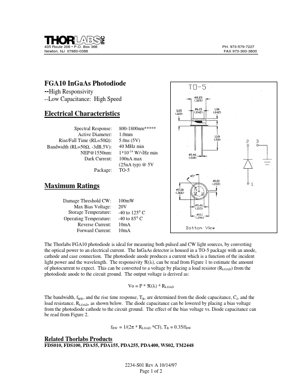
FGA10 In Ga As Photodiode --High Responsivity
--Low Capacitance: High Speed
Electrical Characteristics
Spectral Response: Active Diameter:
Rise/Fall Time (RL=50Ω): Bandwidth (RL=50Ω, -3d B,5V):
NEP@1550nm: Dark Current:
Package:
800-1800nm-
- -
- - 1.0mm 5.0ns (5V)
40 MHz min 1- 10-14 W/√Hz min 100n A max (25n A typ) @ 5V TO-5
Maximum Ratings
Damage Threshold CW: Max Bias Voltage:
Storage Temperature: Operating Temperature:
Reverse Current: Forward Current:
100m W 20V -40 to 125° C -40 to 85° C 10m A 10m A
The Thorlabs FGA10 photodiode is ideal for measuring both pulsed and CW light sources, by converting the optical power to an electrical current. The In Ga As detector is housed in a TO-5 package with an anode, cathode and case connection. The photodiode anode produces a current which is a function of the incident light power and the wavelength. The responsivity ℜ(λ), can be read from Figure 1 to estimate the amount of photocurrent to expect. This can be converted to a voltage by placing a load resistor (RLOAD) from the photodiode anode to the circuit ground. The output voltage is derived as:
Vo = P
- ℜ(λ)
- RLOAD
The bandwidth, f BW, and the rise time response, TR, are determined from the diode capacitance, CJ, and the load resistance, RLOAD, as shown below. The diode capacitance can be lowered by placing a bias voltage from the photodiode cathode to the circuit ground. The effect of the bias voltage vs. Diode capacitance can be read from Figure 2. f BW = 1/(2π
- RLOAD
- CJ), TR = 0.35/f BW
Related Thorlabs Products
FDS010, FDS100, PDA55, PDA155, PDA255, PDA400, WS02, TM2448
2234-S01 Rev A 10/14/97 Page 1 of 2
Typical Circuit Diagram Typical Plots
Figure 1
Figure 2 2234-S01 Rev A 10/14/97
Page 2 of...