TT6061A
Overview
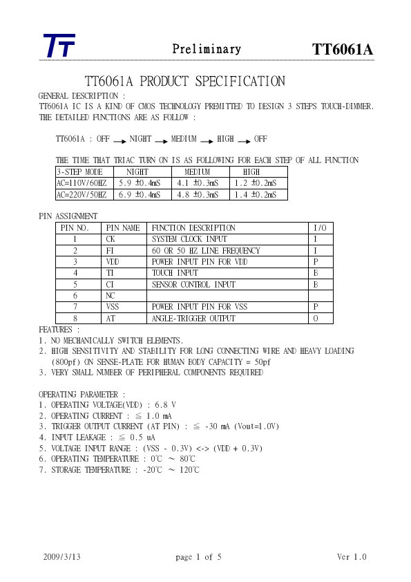
CIRCUIT IDEAS touch signal is connected to the counter/ decoder via a resistor and clock input CK is connected to the counter/decoder via a frequency generator. Line frequency signal is taken through ...
| Part | TT6061A |
|---|---|
| Description | 3 STEPS TOUCH-DIMMER |
| Manufacturer | Tontek Design Technology |
| Size | 56.32 KB |
CIRCUIT IDEAS touch signal is connected to the counter/ decoder via a resistor and clock input CK is connected to the counter/decoder via a frequency generator. Line frequency signal is taken through ...