TOREX SEMICONDUCTOR XC9111
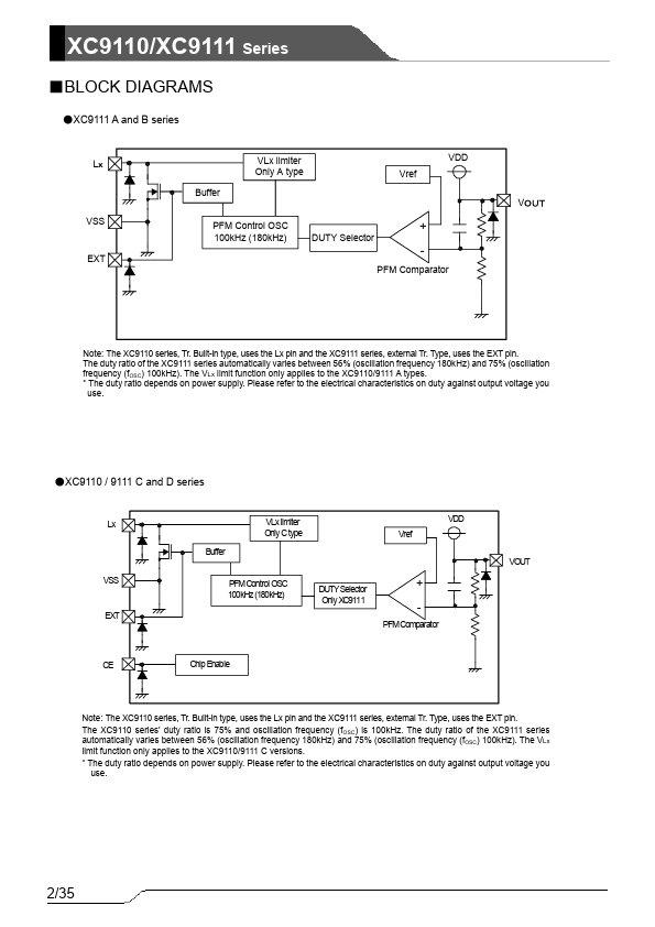
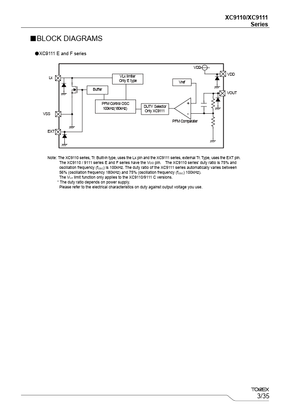
the XC9111 series.) Options include products equipped with a CE pin (C and D versions) that allows the IC to be shut down thereby reducing supply current and with separated VDD/VOUT pins (E and F versions) to separate the power supply block and the output voltage detect block. With the XC9110 series, maximum duty cycle is set to 75% (VDD=3.3V) making it suitable for use with large current operations. The XC9111 series automatically switches duty ratio between 56% & 75% (VDD=3.3V) when it senses changes in load to drop output ripple voltage and can support both large and small currents.| Part No. | XC9111 |
|---|---|
| Datasheet | XC9111 Download |
| Manufacturer |  TOREX SEMICONDUCTOR |
| Description | PFM Controlled Step-Up DC/DC Converter/Controller |
| Buy | Stock & Price |
GENERAL DESCRIPTION
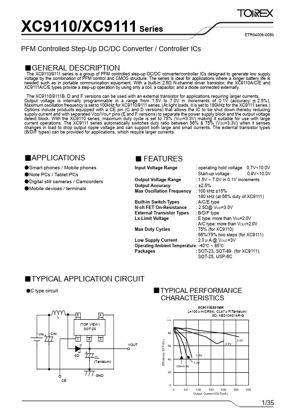
The XC9110/9111 series is a group of PFM controlled step-up DC/DC converter/controller ICs designed to generate low supply voltage by the combination of PFM control and CMOS structure. The series is ideal for applications where a longer battery life is needed such as in portable communication equipment. With a built-in 2.5Ω N-channel driver transistor, the XC9110A/C/E and XC9111A/C/E types provide a step-up operation by using only a coil, a capacitor, and a diode connected externally. The XC9110/9111B, D and F versions can be used with an external transistor for applications requiring larger currents. Output voltage is internally programmable in a range from 1.5V to 7.0V in increments of 0.1V (accuracy: ± 2.5%). Maximum oscillation frequency is set to 100kHz for XC9110/9111 series. (At light loads, it is set to 180kHz for The external transistor types (B/D/F types) can be provided for applications, which require larger currents.●
APPLICATIONS
●Smart phones / Mobile...