MG300Q2YS65H
MG300Q2YS65H is IGBT Module Silicon N Channel IGBT manufactured by Toshiba.
..
TOSHIBA IGBT Module Silicon N Channel IGBT
High Power & High Speed Switching Applications
- -
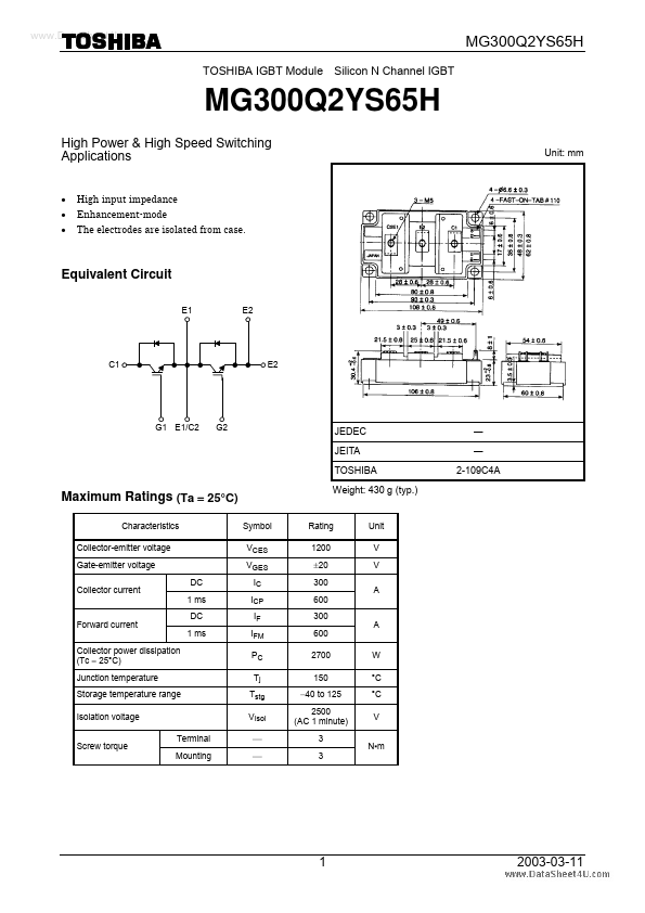
- High input impedance Enhancement-mode The electrodes are isolated from case. Unit: mm
Equivalent Circuit
E1 E2
C1
E2
G1 E1/C2
G2
JEDEC JEITA TOSHIBA
― ― 2-109C4A
Maximum Ratings (Ta = 25°C)
Characteristics Collector-emitter voltage Gate-emitter voltage Collector current DC 1 ms DC 1 ms Symbol VCES VGES IC ICP IF IFM PC Tj Tstg VIsol Terminal Mounting ¾ ¾
Weight: 430 g (typ.)
Rating 1200 ±20 300 600 300 600 2700 150 -40 to 125 2500 (AC 1 minute) 3 3
Unit V V A
Forward current Collector power dissipation (Tc = 25°C) Junction temperature Storage temperature range Isolation voltage Screw torque
A W °C °C V N- m
2003-03-11
Electrical Characteristics (Ta = 25°C)
Characteristics Gate leakage current Collector cut-off current Gate-emitter cut-off voltage Collector-emitter saturation voltage Input capacitance Turn-on delay time Rise time Switching time Turn-on time Turn-off delay time Fall time Turn-off time Forward voltage Reverse recovery time Thermal resistance Turn-on Switching loss Turn-off Symbol IGES ICES VGE (off) VCE (sat) Cies td (on) tr ton td (off) tf toff VF trr Rth (j-c) Eon Eoff IF = 300 A, VGE = 0 IF = 300 A, VGE = -10 V, di/dt = 1000 A/ms Transistor stage Diode stage Inductive load VCC = 600 V, IC = 300 A VGE = ±15 V, RG = 2.7 W Tc = 125°C Inductive load VCC = 600 V, IC = 300 A VGE = ±15 V, RG = 2.7 W Test Condition VGE = ±20 V, VCE = 0 VCE = 1200 V, VGE = 0 VCE = 5 V, IC = 300 m A IC = 300 A, VGE = 15 V Tc = 25°C Tc = 125°C Min ¾ ¾ 4.0 ¾ ¾ ¾ ¾ ¾ ¾ ¾ ¾ ¾ ¾ ¾ ¾ ¾ ¾ ¾ Typ. ¾ ¾ ¾ 3.0 3.6 25600 0.08 0.09 0.17 0.55 0.05 0.60 2.4 0.15 ¾ ¾ 30 26 Max ±500 2.0 7.0 4.0 ¾ ¾ ¾ ¾ ¾ ¾ 0.15 ¾ 3.0 ¾ 0.045 0.1 ¾ ¾ m J V ms °C/W ms Unit n A m A V V p F
VCE = 10 V, VGE = 0, f = 1 MHz
Note: Switching time measurement circuit and input/output waveforms
RG -VGE IC RG
VGE 0
90% 10% trr
VCC IC VCE 0 10% td (off) toff...