MIG100J101H
MIG100J101H is N-Channel IGBT manufactured by Toshiba.
TOSHIBA Intelligent Power Module Silicon N Channel IGBT
High Power Switching Applications Motor Control Applications l Integrates inverter & control circuits (IGBT drive units, protection units for over-current, under-voltage & over-temperature) in one package. l The electrodes are isolated from case. l High speed type IGBT : VCE (sat) = 2.5 V (Max.) toff = 3.0 µs (Max.) trr = 0.30 µs (Max.) l Outline : TOSHIBA 2-110A1A l Weight : 520 g
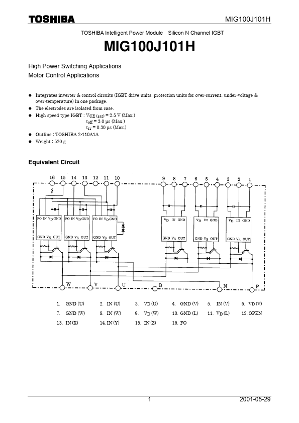
Equivalent Circuit
1. 7.
GND (U) GND (W)
2. IN (U) 8. IN (W) 14. IN (Y)
3. 9.
VD (U) VD (W)
4. GND (V) 10. GND (L) 16. FO
5.
IN (V)
6. VD (V) 12. OPEN
11. VD (L)
13. IN (X)
15. IN (Z)
2001-05-29
Maximum Ratings (Tj = 25°C)
Stage Characteristic Supply voltage Collector-emitter voltage Inverter Collector current Forward current Collector power dissipation Junction temperature Control supply voltage Control Input voltage Fault output voltage Fault output current Operating temperature Module Storage temperature range Isolation voltage Screw torque Condition P-N power terminal ― Tc = 25°C, DC Tc = 25°C, DC Tc = 25°C ― VD-GND terminal IN-GND terminal FO-GND (L) terminal FO sink current ― ― AC 1 minute, M5 Symbol VCC VCES IC IF PC Tj VD VIN VFO IFO TC Tstg VISO ― Ratings 450 600 100 100 300 150 20 20 20 14
- 20 ~ +100
- 40 ~ +125 2500 3 Unit V V A A W °C V V V m A °C °C V N- m
Electrical Characteristics (Tj = 25°C) a. Inverter Stage
Characteristic Collector cut-off current Symbol ICEX Test Condition VCE = 600 V Tj = 25°C Tj = 125°C Min ― ― ― ― ― ― 0V (Note 1) ― ― ― Typ. ― ― 2.0 2.0 2.1 1.0 1.7 0.2 0.1 Max 1 20 2.5 ― 3.3 2.0 3.0 0.5 0.3 µs V V Unit m A
Collector-emitter saturation voltage Forward voltage
VCE (sat) VF ton
VD = 15 V, IC = 100 A Tj = 25°C VIN = 15 V → 0 V Tj = 125°C IF = 100 A VCC = 300 V, IC = 100 A VD = 15 V, VIN = 15 V Inductive load
Switching time toff tf trr
2001-05-29
MIG100J101H b. Control Stage (Tj = 25°C)
Characteristic Control circuit current High side Low...