SSM3J46CTB Overview
Key Specifications
Package: SMD/SMT
Mount Type: Surface Mount
Pins: 3
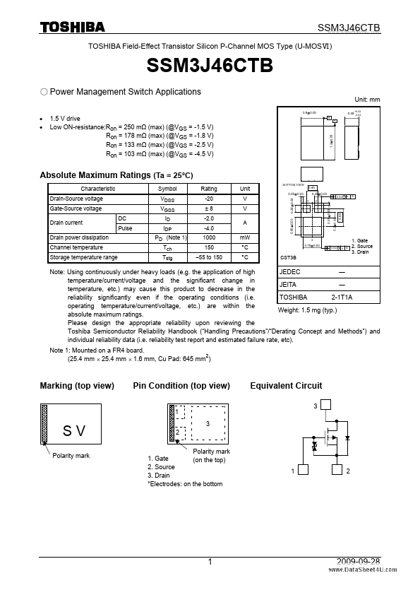
Max Operating Temp: 150 °C
| Part | SSM3J46CTB |
|---|---|
| Description | Power Management Switch Applications |
| Category | Power Management IC |
| Manufacturer | Toshiba |
| Size | 235.34 KB |
Package: SMD/SMT
Mount Type: Surface Mount
Pins: 3
Max Operating Temp: 150 °C
| Seller | Inventory | Price Breaks | Buy |
|---|---|---|---|
| Component Stockers USA | 30 | 1+ : 0.56 USD 10+ : 0.44 USD |
View Offer |
| Win Source | 3520 | 250+ : 0.2356 USD 600+ : 0.194 USD 930+ : 0.1871 USD 1275+ : 0.1813 USD |
View Offer |
| Part Number | Manufacturer | Description |
|---|---|---|
| I.MX31 | Freescale Semiconductor | Multimedia Applications Processors |
| i.MX28 | NXP Semiconductors | Applications Processors |
| i.MX35 | Freescale Semiconductor | Applications Processors |