TA4012AFE
TA4012AFE is TOSHIBA Bipolar Linear Integrated Circuit Silicon Monolithic manufactured by Toshiba.
TOSHIBA Bipolar Linear Integrated Circuit Silicon Monolithic
UHF Wide Band Amplifier Applications Features
- -
- Low current: ICC = 6.5 m A Wide band: f = 2.0 GHz (3d B down) Operating supply voltage: VCC = 1.5~2.2 V
Maximum Ratings (Ta = 25°C)
Characteristics Supply voltage 1 Supply voltage 2 Total power dissipation Operating temperature Storage temperature (Note1) (Note2) Symbol VCC1 VCC2 PD Topr Tstg Rating 2.2 3 300 -40~85 -55~150 Unit V V m W °C °C
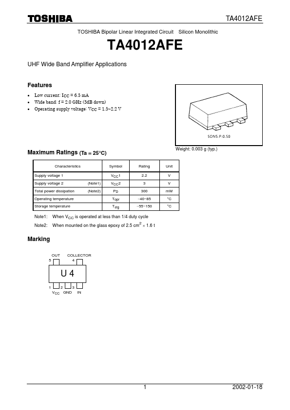
Weight: 0.003 g (typ.)
Note1: Note2:
When VCC is operated at less than 1/4 duty cycle When mounted on the glass epoxy of 2.5 cm ´ 1.6 t
Marking
OUT 5 COLLECTOR 4
U4
1 2 3 VCC GND IN
2002-01-18
Electrical Characteristics (Ta = 25°C, Zg = Zl = 50 W)
Characteristics Circuit current Band width Insertion gain Noise figure Isolation Input return loss Output return loss Output power at 1 d B gain pression Symbol ICC BW ïS21ï NF ïS12ï ïS11ï ïS22ï
2 2 2 2
Test Condition VCC = 2 V, non carrier VCC = 2 V VCC = 2 V, f = 1.5 GHz VCC = 2 V, f = 1.5 GHz VCC = 2 V, f = 1.5 GHz VCC = 2 V, f = 1.5 GHz VCC = 2 V, f = 1.5 GHz VCC = 2 V, f = 1.5 GHz 2 (Note3)
Min 4.5 1.8 10 ¾ ¾ ¾ ¾ ¾
Typ. 6.5 2.0 12 6 -22 -6.5 -7.5 0
Max 8.5 ¾ ¾ 7.5 ¾ ¾ ¾ ¾
Unit m A GHz d B d B d B d B d B d Bm W
Po1d B
Note3:
BW is the frequency of 3d B down from ïS21ï at 1.5 GHz.
Caution
This device is sensitive to electrostatic discharge. When using this device, please ensure that all tools and equipment are earthed.
RF Test Circuit (top view)
VCC 1000 p F 100 p F 1000 p F 10000 p F GND 1000 p F RF IN 1 5 RF OUT
L: 4...