TA8415P
TA8415P is manufactured by Toshiba.
TOSHIBA BIPOLAR LINEAR INTEGRATED CIRCUIT SILICON MONOLITHIC
STEPPING MOTOR CONTROLLER / DRIVER
The TA8415P is general purpose unipolar stepping motor controller / driver, applicable to 3 / 4 phase motors and 1, 1- 2, 2 phase excitation drive by initial setting of control terminals.
Features l 1 chip stepping motor controller / driver. l 3 or 4 phase and 1, 1- 2, 2 phase excitation drive are available. l CW / CCW rotation and 1 clock or 2 clock drive are available. l Hysteresis is provided with clock, CW / CCW, reset inputs for noise protection. l Output enable, initial detect are available. l Output current up to 400mA (MAX.)
BLOCK DIAGRAM
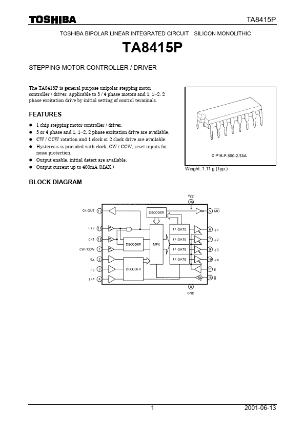
Weight: 1.11 g (Typ.)
1...